
touch panel

A touch panel and touch signal technology, applied in the direction of instruments, electrical digital data processing, data processing input/output process, etc., can solve the problems of height difference, electrode layer disconnection, etc., so as to avoid affecting the appearance and electrode Layer Breakline Effect

Active Publication Date: 2016-12-28
ACER INC
View PDF4 Cites 0 Cited by
  • Summary
  • Abstract
  • Description
  • Claims
  • Application Information

AI Technical Summary

Problems solved by technology

However, the surface of the visual shielding layer in the non-display area needs to have a height difference from the surface of the display area
When the electrode layer is arranged on the surface of the visual shielding layer and the surface of the display area, the height difference between the visual shielding layer and the display area will easily lead to disconnection of the electrode layer

Method used


Image

  • touch panel
  • touch panel
  • touch panel

Examples


Embodiment Construction

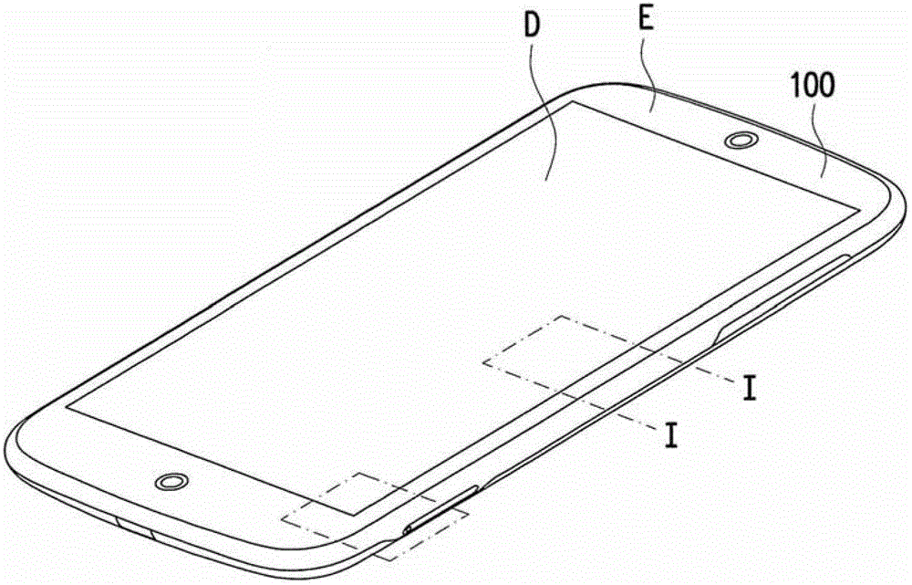
[0039] Figure 1A It is a schematic diagram of a touch panel according to an embodiment of the present invention. Figure 1B for Figure 1A A cross-sectional view of the touch panel along line I-I. Figure 1C for Figure 1B exploded diagram. Please refer to Figures 1A to 1C , the touch panel 100 of this embodiment is used to provide touch signals. The touch panel 100 includes a substrate 110 , a first visual shielding layer 120 , an electrode layer 130 , a metal material layer 140 and a second visual shielding layer 150 . The substrate 110 has a surface 112 . The first visual shielding layer 120 is disposed on at least one edge region E of the surface 112 .

[0040] After the first visual shielding layer 120 is set, the electrode layer 130 is set on the surface 112 of the substrate 110 . Wherein, the first portion of the electrode layer 130 is disposed on the display area D adjacent to the edge area E on the surface 112 , and the second portion of the electrode layer 13...


PUM


Abstract

The invention provides a touch panel for providing touch signals. The touch panel includes a substrate, a first visual shielding layer, an electrode layer, a metal material layer and a second visual shielding layer. The substrate has a surface, and the first visual shielding layer is disposed on at least one edge region of the surface. A part of the electrode layer is disposed on the display area adjacent to the edge area on the surface, and another part of the electrode layer covers at least a part of the first visual shielding layer. The metal material layer is disposed on the edge area and is electrically connected to the electrode layer. The second visual shielding layer is disposed on the edge area and stacked on the first visual shielding layer. The other part of the electrode layer is interposed between the first visual shielding layer and the second visual shielding layer.

Description

technical field [0001] The present invention relates to a touch panel, and in particular to a touch panel with a visual shielding layer. Background technique [0002] In recent years, with the development of the technology industry, electronic devices such as notebook computers (Notebook, NB for short), tablet computers (Tablet PC) and smart phones (Smart Phone) have frequently appeared in daily life. Among them, some electronic devices are light, thin and small, so that users can operate them by hand and carry them easily. The types and functions of electronic devices are becoming more and more diverse. The convenience and practicality make these electronic devices more popular and can be used for different purposes. Therefore, the user can hold the electronic device with one hand and operate the electronic device by touching or pressing the keyboard or touch panel on the operating surface of the electronic device. [0003] Such electronic devices have electrode layers di...

Claims


Application Information

Patent Timeline
Patent Type & Authority Patents(China)
IPC IPC(8): G06F3/041
Inventor 郭峻廷
Owner ACER INC
Learn More