Connector assembly

A technology of connector assembly and locking assembly, which is applied in the direction of connection, parts of connecting device, two-part connecting device, etc., can solve the problems of rising production cost of connector assembly, influence of assembly efficiency, etc., to simplify the structure and improve assembly efficiency. Effect

Inactive Publication Date: 2014-08-27
HARTING ZHUHAI MFG
View PDF3 Cites 8 Cited by
  • Summary
  • Abstract
  • Description
  • Claims
  • Application Information

AI Technical Summary

Problems solved by technology

[0010] However, the above-mentioned locking device includes many components with complex structures. The multiple components not only affect the assembly efficiency, but also increase the production cost of the connector assembly due to the need to purchase or produce multiple different components.

Method used


Image

  • Connector assembly
  • Connector assembly
  • Connector assembly

Examples


no. 1 example

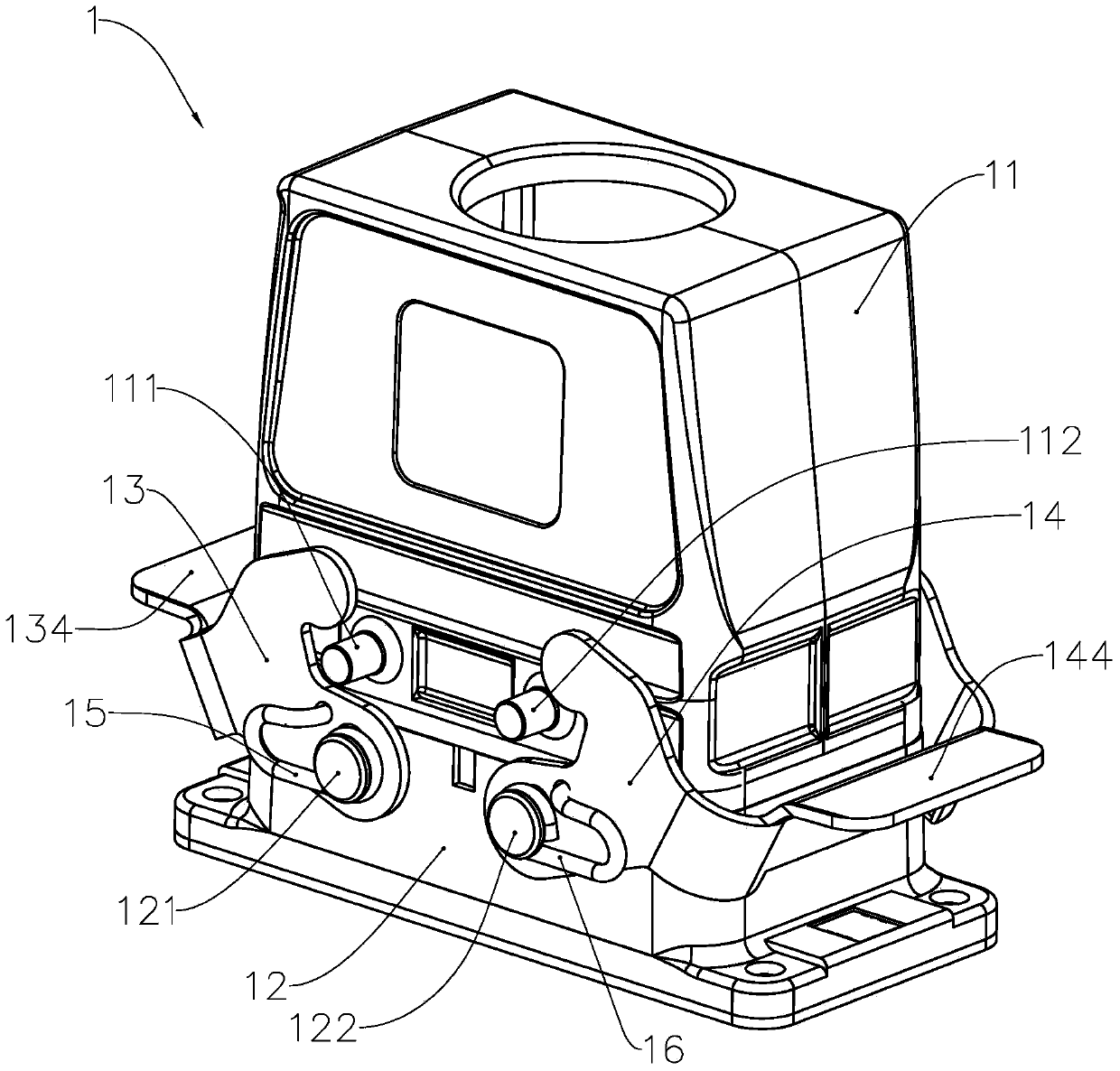
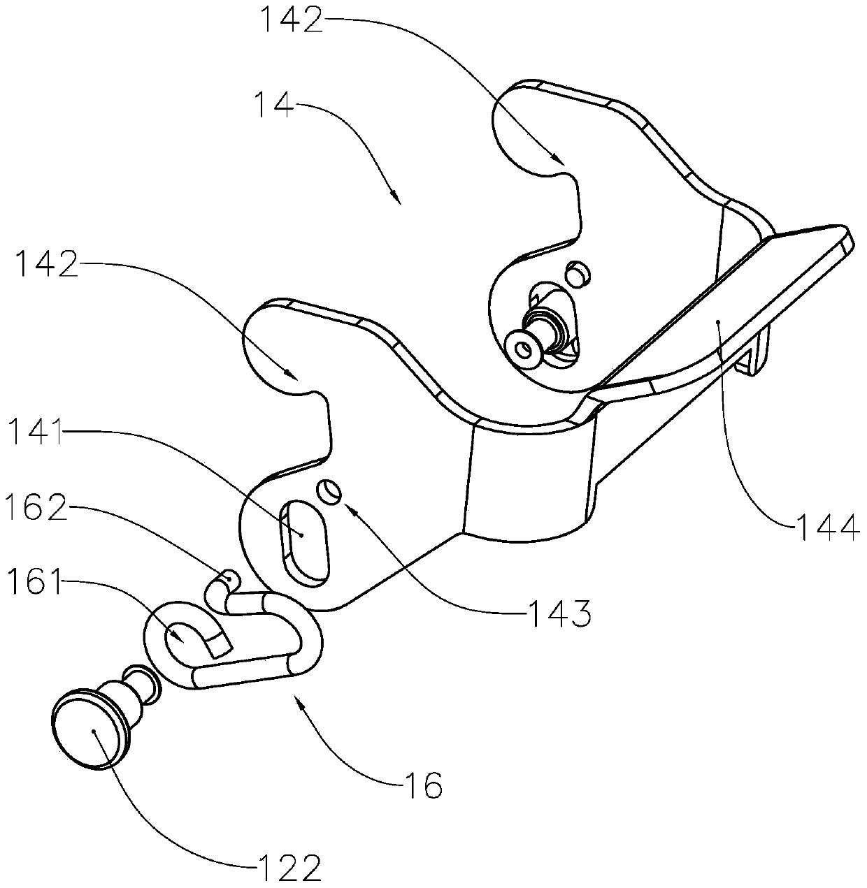
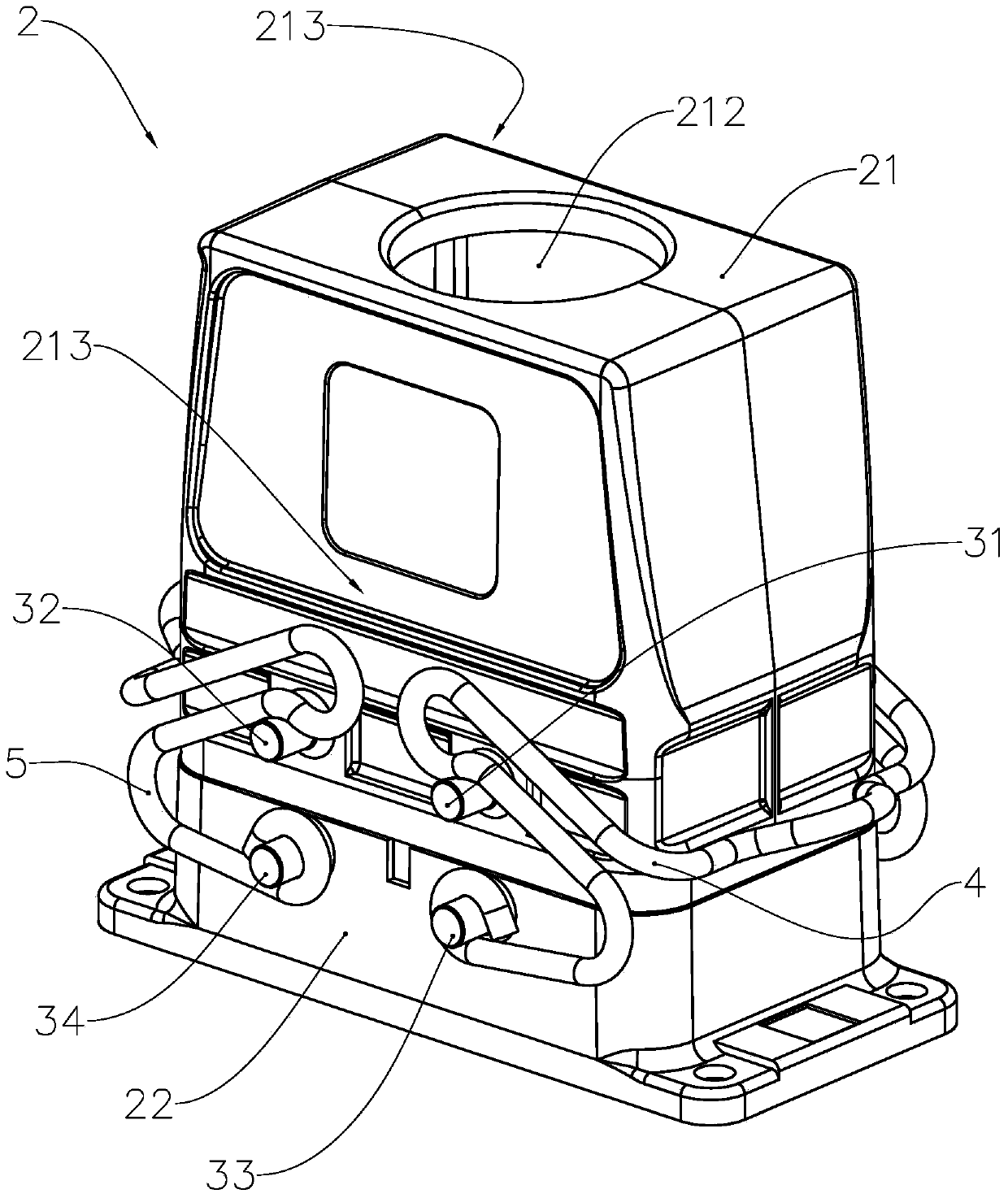
[0041] refer to image 3 , Figure 4 and Figure 5 , image 3 and Figure 4 is a structural diagram of the connector assembly 2 under different viewing angles, Figure 5is an exploded view of the connector assembly 2. The connector assembly 2 includes a plug 21, a receptacle 22 and two locking assemblies. The plug 21 includes a housing, which encloses a wire accommodation chamber, an opening 211 is opened at the lower end of the wire accommodation chamber, and an opening 211 is opened at the upper end of the wire accommodation chamber. Opening 212, a first wiring seat (not shown) is provided at the opening 211, and a cable hub (not shown) is provided at the opening 212. After the cable passes through the cable hub, the multiple wires in the cable respectively connected to the corresponding first wiring socket. The socket 12 includes a base, the base encloses a cavity for accommodating a wire socket, an opening 221 is opened at the upper end of the cavity, and a second wi...

no. 2 example

[0057] refer to Figure 10 , Figure 10 It is a structural diagram of the second embodiment of the connector assembly. On the basis of the first embodiment of the connector assembly, the locking member 5 can also be as Figure 10 In the structure shown, the difference between the locking member 5 and the locking member 4 lies in the setting of the operating part 55 and the positioning part 511. Compared with the operating part 45, the operating part 55 has a larger contact position, specifically, the operation The part 55 is arranged in a U-shaped structure, and the U-shaped operating part 55 has a protrusion 551 extending outward on the outer side of the side wall, and the protrusion 551 is arranged in a right-angled U-shaped structure, and the protrusion 551 and the operating part 55 are arranged on the same On the plane, it is beneficial to reduce processing difficulty and improve production efficiency. The U-shaped protrusion 551 with a larger contact position is used by...


PUM


Abstract

The invention provides a connector assembly which comprises a plug, a socket and two locking assemblies. The plug comprises a shell and is provided with a first wire holder, the socket is provided with a second wire holder connected with the first wire holder, and each locking assembly comprises two fixing columns, two first locating parts and a lock catch piece, wherein the two fixing columns are oppositely arranged on the plug, the two first locating parts are oppositely arranged on the socket, and the lock catch piece comprises two second locating parts, two locking parts, two elastic parts and an operation part, each second locating part is matched with the corresponding first locating part, the second locating parts can rotate around the first locating parts, each locking part and the corresponding fixing column are combined in a clamped mode, the elastic parts are arranged between the corresponding second locating parts and the corresponding locking parts which are located on the same sides, the operation part is arranged between the two locking parts, and the second locating parts, the elastic parts, the locking parts and the operation part are of sequentially-connected bend-rod-shaped structures. By means of the sequentially-connected bend-rod-shaped structures, the structure of the connector assembly is simplified, and the assembly efficiency is improved.

Description

technical field [0001] The invention relates to the field of electrical connection devices, in particular to a connector assembly. Background technique [0002] A connector component is a commonly used component in electrical engineering. Its function is to connect circuits on different devices or connect different modules in the circuit, so that current or signals can flow or be transmitted, and the circuit can achieve predetermined functions. The existing connector assembly includes a plug and a socket, and the connection method is generally that the plug is inserted into the socket, that is, the electrical connection terminals in the plug are electrically connected with the electrical connection terminals in the socket. [0003] refer to figure 1 , figure 1 It is an existing connector assembly 1. The connector assembly 1 includes a socket 12 and a plug 11 installed above the socket 12. The housing of the plug 11 encloses an accommodating cavity for accommodating wires. ...

Claims


Application Information

Patent Timeline
Patent Type & Authority Applications(China)
IPC IPC(8): H01R13/639H01R24/00
Inventor 黎桂新
Owner HARTING ZHUHAI MFG
Why Eureka
Try Eureka