Short connecting device

A short-circuit and plug-in rod technology, which is applied to the parts of the connection device, coupling device, connection, etc., can solve the problems of open circuit of the secondary circuit of the current transformer, easy loosening of the short-circuit joint, and endangering personal safety, etc. Productivity, Convenience, and Reliable Connections

Active Publication Date: 2014-08-27
STATE GRID SICHUAN ELECTRIC POWER
View PDF8 Cites 12 Cited by
  • Summary
  • Abstract
  • Description
  • Claims
  • Application Information

AI Technical Summary

Problems solved by technology

[0004] However, the existing shorting joints have the problem of unstable fixation after insertion, and the shorting joints are easy to loosen, causing the secondary circuit of the current transformer to open, generating high voltage to burn down the equipment and even endanger personal safety
[0005] Moreover, the existing short-connector can only be removed from the jack of the secondary circuit of the current transformer before the short-circuit can be canceled, which causes inconvenience to the work

Method used


Image

  • Short connecting device
  • Short connecting device
  • Short connecting device

Examples


Embodiment 1

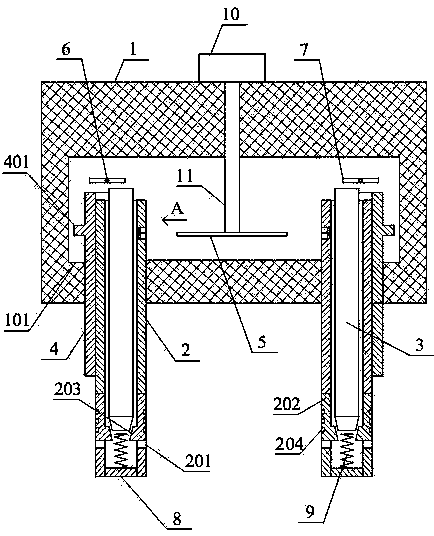
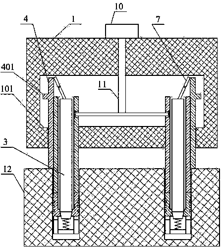
[0034] Such as Figure 1~Figure 4 As shown, a shorting device includes a fixed body 1, an insertion rod 2, an expansion rod 3, a sliding half-circle sleeve 4, a conduction bar 5, a rotating shaft 6 and a pressing bar 7, a knob 10 and a connecting shaft 11; the insertion rod 2 It is a hollow cylinder, and the outer surface of the insertion rod 2 is provided with a symmetrical hole 201, and an expansion strip 202 is arranged in the hole 201. The upper end of the expansion strip 202 is connected with the hole wall of the hole 201, and the other parts of the expansion strip 202 are not connected with the hole. The hole wall of 201 contacts, and the inner surface of the expansion bar 202 is provided with a protrusion 203; the expansion rod 3 is slidably arranged in the insertion rod 2, the top of the expansion rod 3 is located outside the insertion rod 2, and the bottom end of the expansion rod 3 is Tapered, the bottom end of the expansion rod 3 is located above the protrusions 203...

Embodiment 2

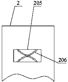
[0039] Such as figure 1 and figure 2 As shown, this embodiment is based on Embodiment 1, and the outer surface of the expansion strip 202 is provided with a plurality of anti-slip grooves 204 .

Embodiment 3

[0041] Such as figure 1 and figure 2 As shown, this embodiment is based on any one of the above-mentioned embodiments, the bottom end of the insertion rod 2 is provided with a sealing plate 8 ; and a spring 9 fixed on the upper surface of the sealing plate 8 is also included.

[0042] After the short-circuit plug is inserted into the secondary circuit socket 10 of the current transformer, the bottom end of the expansion rod 3 compresses the spring 9, and after the short-circuit plug is taken out, the spring 9 pushes the expansion rod 3 upward, so that the bottom end of the expansion rod 3 is separated The protruding part 203, the expansion rod 3 and the expansion strip 202 automatically reset.


PUM


Abstract

The invention discloses a short connecting device which comprises a fixing body, inserting connection rods, expansion rods, a sliding semicircular sleeve, a breakover bar and a rotary knob. Holes are formed in the outer surfaces of the inserting connection rods, the expansion rods are arranged in the holes, and protrusion parts are arranged on the expansion rods. The expansion rods are arranged in the inserting connection rods in a sliding mode, the top ends of the inserting connection rods are fixed in the fixing body, and the sliding semicircular sleeve is in sliding contact with the outer surfaces of the inserting connection rods. A rotating shaft is fixed in the fixing body, and the rotating shaft is placed above the inserting connection rods. The middle portion of a pressing bar is fixed on the rotating shaft, and the two ends of the pressing bar are in contact with the top end of the sliding semicircular sleeve and the top ends of the expansion rods respectively. The number of the inserting connection rods is two. A connecting shaft is vertically arranged in the fixing body, and the connecting shaft is placed between the two inserting connection rods. The middle portion of the breakover bar is connected with the connecting shaft, and the rotary knob is arranged on the top of the fixing body and is connected with the connecting shaft. The inserting connection rods are further provided with connecting grooves and arc-shaped metal pieces. The short connecting device can be firmly mounted, and quick switching of a short connection state and a non-short connection state can be achieved.

Description

technical field [0001] The invention relates to the field of electric power maintenance, in particular to a short circuit device. Background technique [0002] In relay protection work, it is often necessary to short-circuit the secondary circuit of the current transformer. [0003] At present, the secondary circuit of the current transformer is mainly short-circuited by using a short-circuit joint. The existing shorting joint includes a joint body and two insertion rods arranged on the joint body, and the two insertion rods are connected to each other. When in use, insert the plug-in rod into the socket of the secondary circuit of the current transformer to realize short-circuiting. [0004] However, the existing shorting joints have the problem of unstable fixation after insertion, and the shorting joints are easy to loosen, causing the secondary circuit of the current transformer to open, generating high voltage to burn down the equipment and even endangering personal s...

Claims


Application Information

Patent Timeline
Patent Type & Authority Applications(China)
IPC IPC(8): H01R31/08H01R13/639H01R13/71H01R13/10
Inventor 陈晖
Owner STATE GRID SICHUAN ELECTRIC POWER
Why Eureka
Try Eureka