Method for dynamically setting gateway reactive power control range under single-line and single-variable wiring mode

A wiring method and power control technology, applied in the direction of reactive power adjustment/elimination/compensation, reactive power compensation, etc., can solve the problem of unreasonable reactive power control range at the gate

Inactive Publication Date: 2014-08-27
SOUTH CHINA UNIV OF TECH
View PDF2 Cites 9 Cited by
  • Summary
  • Abstract
  • Description
  • Claims
  • Application Information

AI Technical Summary

Problems solved by technology

[0005] The purpose of the present invention is to solve the problem of unreasonable control range of reactive power at the gate caused by changes in the load level of the power grid, and p

Method used


Image

  • Method for dynamically setting gateway reactive power control range under single-line and single-variable wiring mode
  • Method for dynamically setting gateway reactive power control range under single-line and single-variable wiring mode
  • Method for dynamically setting gateway reactive power control range under single-line and single-variable wiring mode

Examples


Embodiment Construction

[0041] The specific implementation of the present invention will be further described below with reference to the drawings and examples, but the implementation and protection of the present invention are not limited to this.

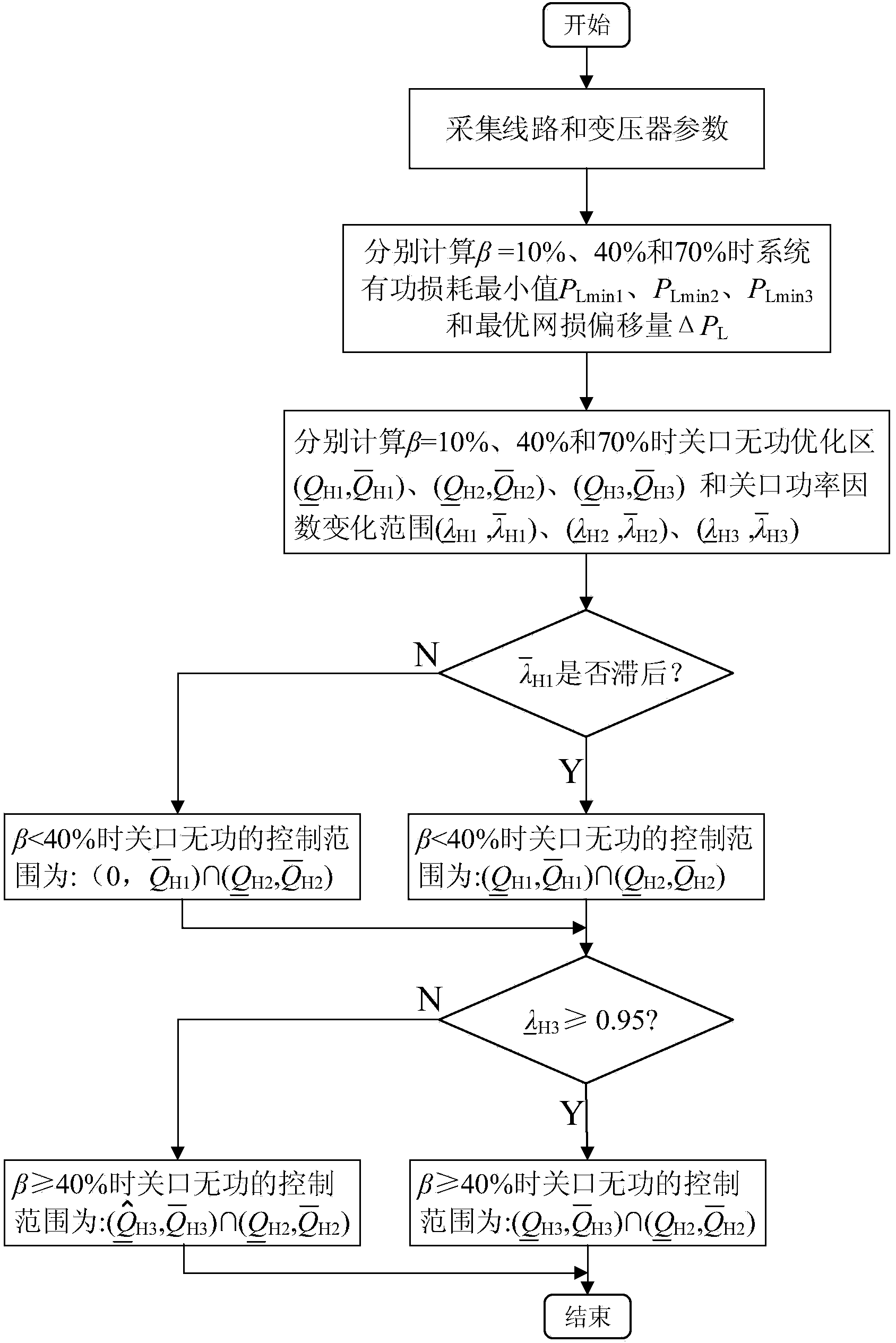
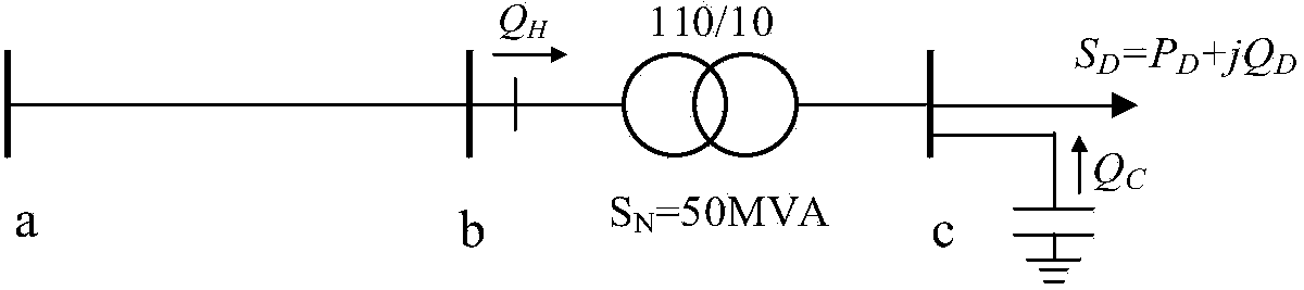
[0042] Such as figure 1 , A method for dynamically setting the reactive power control range of the gateway in a single-line single-variable wiring mode, including the following steps:

[0043] (1) Collect line resistance r, reactance x, node susceptance B, and transformer capacity S N , No-load loss P 0 , Load loss P k , Short-circuit voltage percentage U k %, the percentage value of no-load current I 0 % And its transmitting terminal voltage U a ;

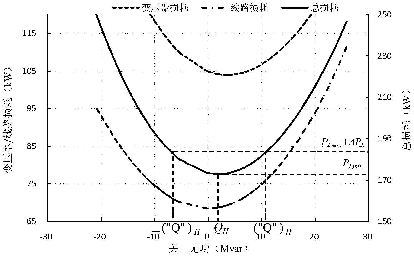
[0044] (2) Choose three levels of transformer load factor β = 10%, 40% and 70% to represent the lighter load state 1, the medium load state 2 and the heavier load state 3. Use the drawing method to find the three load states respectively The minimum value of the sum of the active power loss of the line and the tra...


PUM


Abstract

The invention provides a method for dynamically setting a gateway reactive power control range under a single-line and single-variable wiring mode. The problem that the dynamic variation of power grid operation characteristics can not be adapted due to the fact that the gateway reactive power control range is fixed in automatic voltage control of a current power grid is solved. The method comprises the specific steps that first, the parameter of a regional power grid circuit, the parameter of a main transformer and the voltage data of an electricity sending end are collected; second, the minimum value of system active power loss of the main transformer under different load rates, the gateway reactive power optimal section, and the corresponding gateway power factor variation range are calculated; at last, the gateway power factor constraints of the transformer in the low load process and in the heavy load process are considered, and the gateway reactive power control ranges under different working conditions are obtained. According to the method for dynamically setting the gateway reactive power control range under the single-line and single-variable wiring mode, the gateway reactive power optimal control range can be dynamically adapted to the variation of power grid load levels, and reactive power balance, energy saving and consumption reduction of the system can be promoted.

Description

Technical field [0001] The invention relates to a gateway reactive power control method of a power system, in particular to a method for dynamically setting a gateway reactive power control range in a single-line single-variable connection mode. Background technique [0002] With the continuous expansion of the power grid, the safety, reliability, and economic issues of grid operation have become more prominent. The traditional method of centralized optimization after modeling the entire complex large power grid is not only less feasible, but also less effective in control. difference. In comparison, the VQC control strategy based on the local electrical information of the substation and the pursuit of reactive power balance in place, due to the low modeling requirements, less information interaction, and simple control algorithm, is currently obtained in the reactive voltage control on the AVC substation side It has a wide range of applications. [0003] However, this method has...

Claims


Application Information

Patent Timeline
IPC IPC(8): H02J3/18
CPCY02E40/30
Inventor 张勇军羿应棋李钦豪
Owner SOUTH CHINA UNIV OF TECH
Why Eureka
Try Eureka