System and method for assembling a solar cell matrix

A solar cell and matrix technology, applied in the direction of circuits, photovoltaic power generation, electrical components, etc.

Inactive Publication Date: 2014-08-27
佐蒙特股份有限公司
View PDF4 Cites 1 Cited by
  • Summary
  • Abstract
  • Description
  • Claims
  • Application Information

AI Technical Summary

Problems solved by technology

This is obviously not

Method used


Image

  • System and method for assembling a solar cell matrix
  • System and method for assembling a solar cell matrix
  • System and method for assembling a solar cell matrix

Examples


Embodiment Construction

[0092] The following figure is one possible design of the system of the present invention.

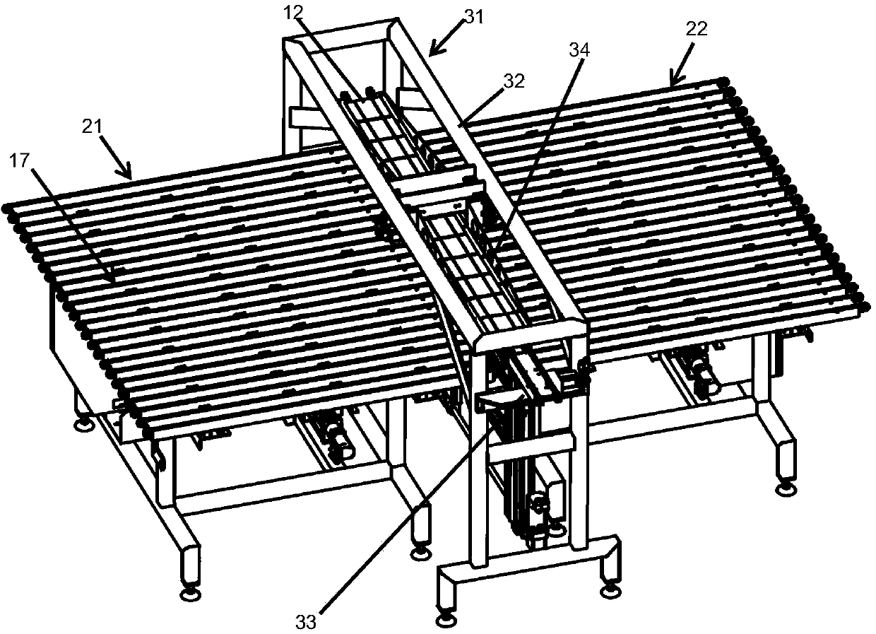
[0093] figure 1 An embodiment system 11 of the invention is shown for forming a solar cell matrix. The system 11 is modular and can be arranged separately according to the process to be performed and / or local possibilities or needs. The system 11 comprises a conveying unit 16 for conveying strings 12 in at least one conveying direction (arrow 19) having an input area 17 at one end and an output area at the other end, the input area 17 being suitable for For receiving the string 12 of solar cells, the output area is adapted to hold the matrix 13 of solar cells. In the present embodiment, a total of five conveyor devices 21 - 25 form the conveyor unit 16 , all of which have the same basic structure and are arranged in a straight line. A spacing is provided between the conveying devices 21-25, and each conveying device conveys the string 12 from one station to the next. Control box 14...


PUM


Abstract

The invention refers to a system (11) for the formation of a matrix(13)of solar cells, having a unit (16) with an input area (17) and an output area(18). Between the input area (17) and the output area (18) the strings (12) are conveyed on the conveying unit (16)in a conveying direction(19). The system (11) further comprising means (31) for placing strings (12) on the input area(17) and rotating means (41, 51, 61) designed to lift a string (12) from the conveying unit (16), rotate that string about axes and lower it onto the same conveying unit (16).The invention refers further to a method using such a system (11).

Description

technical field [0001] The present invention relates to a system and method for assembling a solar cell matrix. Background technique [0002] The solar cell string is formed by a chain composed of solar cells placed in sequence, and is electrically connected to each other by more than two wires, also known as a belt. Typically, a solar string consists of eight to ten cells connected in series. This can be done by hand, but is usually done with welded stringer equipment. Batteries due to their composition usually have a top surface representing the negative electrode and a bottom surface representing the positive electrode. The top side is the optoelectronically active side ("sun side"). Thus, in a string, the wire connects the top surface of one cell to the bottom surface of the next cell. By necessity, the terminal cells of a string have negative or positive polarity. This phenomenon concerns all types of solar cells (including conventional cells, back-contact cells, e...

Claims


Application Information

Patent Timeline
IPC IPC(8): H01L31/18
CPCH01L31/188H01L31/18Y02E10/50
Inventor 格哈德·肯德尔马蒂斯·鲁
Owner 佐蒙特股份有限公司
Why Eureka
Try Eureka