
Modeling lawn shears

A technology of lawn shears and working boxes, which is applied in the field of gardening tools and can solve problems such as lawn monotony

Active Publication Date: 2014-09-03
江苏麦格美节能科技有限公司
View PDF9 Cites 0 Cited by
  • Summary
  • Abstract
  • Description
  • Claims
  • Application Information

AI Technical Summary

Problems solved by technology

Traditional lawn shears and lawn machines are designed to trim the lawn neatly. For lush flower beds and shrubs, the lawn is very monotonous. There is no pair of scissors or machines that can shape the lawn at one time.

Method used


Image

  • Modeling lawn shears
  • Modeling lawn shears

Examples


Embodiment 1

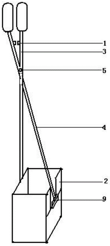
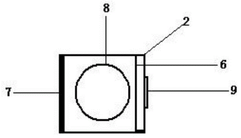
[0028] 1 A model lawn shear, the fixed handle 3 is connected to the working box 2, the fixed handle 3 and the cutting handle 4 are riveted together by the rivet 5, the end of the cutting handle 4 is fixedly connected to the steering block 9, the steering block is connected to the blade 6, and the blade is located in the working box Inside, the blade 6 is placed horizontally, a knife stop wall 7 is provided in the working box, and the mold 8 is located in the working box 2 and below the blade 6 .

[0029] The working box 2 is a cuboid, and the mold 8 is detachably connected with the working box 2 . Die 8 is 4 centimeters with working box 2 bottom distances.

[0030] The knife stop wall 7 is metal. The steering block 5 is detachably connected with the blade 6 . The cutting handle 4 or the fixed handle 3 are provided with a damping block 1 .

[0031] The fixed handle 3 and the cutting handle 4 can be adjusted in length by changing the handle.


PUM


Abstract

The invention relates to a gardening tool, in particular to a pair of modeling lawn shears. A fixed handle is connected with a work box, the fixed handle is connected with a cutting handle in a riveting mode through a rivet, the tail end of the cutting handle is fixedly connected with a steering block, the steering block is connected with a blade, the blade is located in the work box, the blade is arranged in the horizontal direction, a blade stop wall is arranged in the work box, and a mould is located in the work box and under the blade.

Description

technical field [0001] The invention relates to a garden tool, in particular to a modeling lawn shear. [0002] Background technique [0003] With the development of social material culture, people have higher requirements for spiritual life, and greening has become an indispensable part of everyone's life. Lawn occupies a large proportion in greening because it is easy to survive and maintain water and soil. Both traditional lawn shears and lawn machines appeared to trim the lawn neatly. For lush flower beds and shrubs, the lawn is very monotonous. There is no pair of scissors or machines that can make lawn shapes at one time. Contents of the invention [0004] The problem to be solved, aiming at the above problems, the present invention provides a lawn shear capable of shaping the lawn. [0005] Technical solution: The present invention provides a modeling lawn shear, the fixed handle is connected to the working box, the fixed handle and the cutting handle are ri...

Claims


Application Information

Patent Timeline
IPC IPC(8): A01G3/06
Inventor 闻献
Owner 江苏麦格美节能科技有限公司
Learn More