Steel pipe flange welding and positioning device

A flange welding and positioning device technology, applied in the direction of auxiliary equipment, welding equipment, auxiliary welding equipment, etc., can solve the problems of high labor intensity, high price, untargeted welding, etc., and achieve convenient docking, welding quality assurance, stable sex control effect

Active Publication Date: 2014-09-03
HEBEI FLEXTRONICS ELECTRICAL TECH
View PDF12 Cites 32 Cited by
  • Summary
  • Abstract
  • Description
  • Claims
  • Application Information

AI Technical Summary

Problems solved by technology

[0005] The technical problem to be solved by the present invention is that the welding quality of the existing manual welding flange and steel pipe is not high, and the labor intensity is high. The existing automatic welding equipment is not targeted for the welding between the steel pipe and the flange, and the structure is complicated. expensive

Method used


Image

  • Steel pipe flange welding and positioning device
  • Steel pipe flange welding and positioning device
  • Steel pipe flange welding and positioning device

Examples


Embodiment Construction

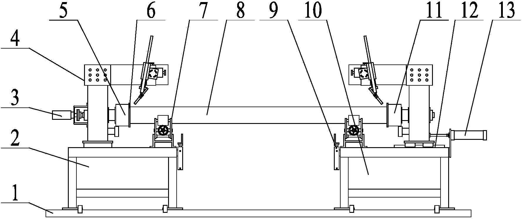
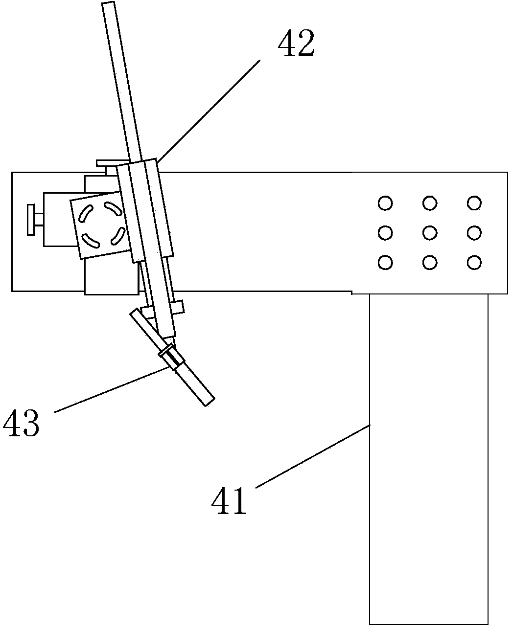
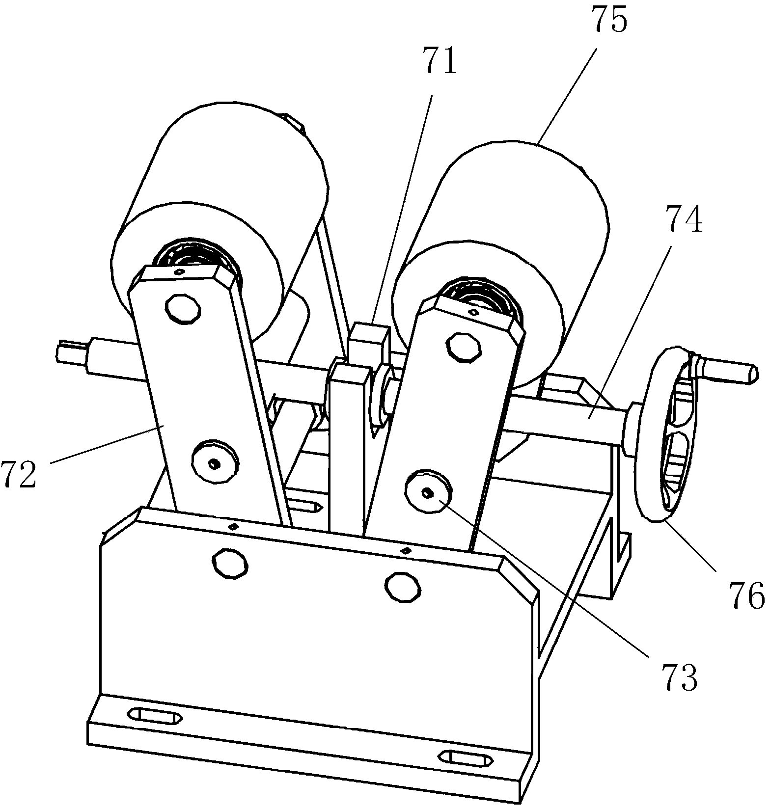
[0022] The specific implementation manners of the present invention will be further described in detail below in conjunction with the accompanying drawings and embodiments. The following examples are used to illustrate the present invention, but are not intended to limit the scope of the present invention. In the description of the present invention, unless otherwise specified, the orientation or state relationship indicated by the terms "inner", "outer", "upper", "lower" and the like are based on the orientation or status relationship shown in the drawings, and are only for the purpose of It is convenient to describe the present invention and simplify the description, but does not indicate or imply that the device or element referred to must have a specific orientation, be constructed and operate in a specific orientation, and thus should not be construed as limiting the present invention.

[0023] In the description of the present invention, it should be noted that unless ot...


PUM


Abstract

The invention relates to the technical field of welding, and provides a steel pipe flange welding and positioning device. The steel pipe flange welding and positioning device comprises a first sliding rail, a first platform and a second platform, wherein the first platform and the second platform are arranged on the first sliding rail in a sliding mode. Limiting devices are arranged between the first platform and the first sliding rail and between the second platform and the first sliding rail. A first fixing jaw and a second fixing jaw which are used for positioning flanges are connected to the first platform and the second platform in a relatively rotating mode, and at least one of the first fixing jaw and the second fixing jaw is driven by a power device to rotate. Roller carriers used for holding steel pipes are arranged at the positions, between the first fixing jaw and the second fixing jaw, of the first platform and the second platform, and the height of the roller carriers is adjustable. The device is ingenious in structural design, is particularly suitable for positioning of steel pipes of various diameters and flanges of various diameters, and can achieve stable welding and guarantee the welding quantity; the steel pipes and the flanges can be positioned conveniently. In addition, the device is simple in structure, low in cost and easy to popularize.

Description

technical field [0001] The invention relates to the field of welding technology, in particular to a steel pipe flange welding device. Background technique [0002] Common transportation pipelines are usually spliced ​​by a large number of steel pipes. Both ends of each steel pipe are welded with flanges, and the steel pipes are connected by flanges. The flange connection is convenient, firm and tight, so it is called Widely used in the connection of steel pipes. [0003] Both the steel pipe and the flange are processed separately, and the flange is welded to both ends of the steel pipe when necessary. At present, the welding of steel pipes and flanges is mostly done by manual welding. Since a large number of steel pipes are used in the transportation pipeline, the labor intensity of manual welding is very huge, and because of the heavy weight of the steel pipes, it cannot be conveniently connected with the method. The flange is used for positioning, and the welding personn...

Claims


Application Information

Patent Timeline
Patent Type & Authority Applications(China)
IPC IPC(8): B23K37/00B23K37/04B23K37/02
CPCB23K37/0276B23K37/04B23K37/053B23K37/0538B23K2101/10
Inventor 李旭魏忠芳王利民
Owner HEBEI FLEXTRONICS ELECTRICAL TECH
Why Eureka
Try Eureka