Supercharge Your Innovation With Domain-Expert AI Agents!

A transmission assembly and a bulk cement semi-trailer

A technology for bulk cement and semi-trailers, which is applied in the direction of auxiliary drive devices, control devices, vehicle components, etc. It can solve problems such as difficulty in disassembly, easy deformation of longitudinal beams, and inability to carry external air sources with the vehicle, so as to reduce deformation, The effect of easy disassembly and installation

Active Publication Date: 2016-08-24
ANHUI XINGMA SPECIAL PURPOSE VEHICLE
View PDF8 Cites 0 Cited by
  • Summary
  • Abstract
  • Description
  • Claims
  • Application Information

AI Technical Summary

Problems solved by technology

The external air source has the advantages of high efficiency and low cost, but the external air source cannot be carried with the vehicle and cannot meet the needs of different working conditions. Therefore, when there is no external air source available, the diesel engine and The transmission of the air compressor to provide compressed air
[0003] In the prior art, in order to reduce the weight of the vehicle body and improve fuel economy, a detachable transmission device is generally used, and it is removed when it is not needed to reduce the weight of the vehicle body and achieve the purpose of saving fuel. The current detachable transmission device generally consists of two A cantilever beam structure composed of longitudinal beams detachably installed on the tank seat of the bulk cement semi-trailer is used to support the entire transmission device. The longitudinal beams need to bear a large bending moment, and the requirements for the longitudinal beams are high. During the production and use , the longitudinal beam is easily deformed, which makes it difficult to disassemble

Method used


Image

  • A transmission assembly and a bulk cement semi-trailer
  • A transmission assembly and a bulk cement semi-trailer
  • A transmission assembly and a bulk cement semi-trailer

Examples


Embodiment Construction

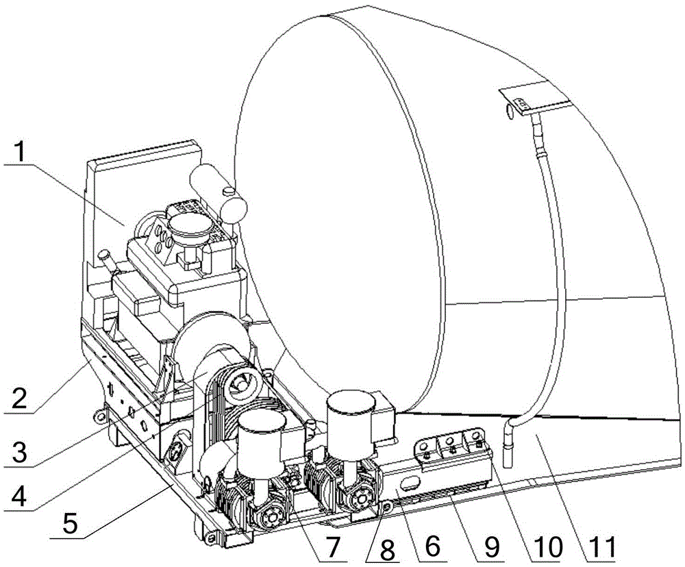
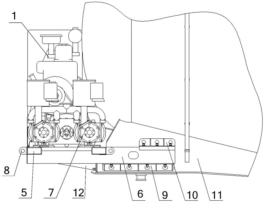
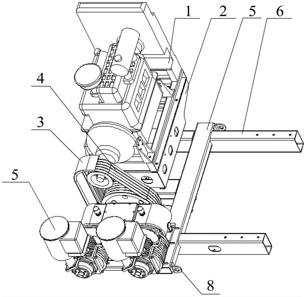
[0033] The invention provides a transmission assembly device and a bulk cement semi-trailer, so that after the transmission assembly device is installed on the bulk cement semi-trailer, it can withstand a large bending moment, reduce deformation, and facilitate installation and disassembly. Purpose.

[0034] The following will clearly and completely describe the technical solutions in the embodiments of the present invention with reference to the accompanying drawings in the embodiments of the present invention. Obviously, the described embodiments are only some, not all, embodiments of the present invention. Based on the embodiments of the present invention, all other embodiments obtained by persons of ordinary skill in the art without making creative efforts belong to the protection scope of the present invention.

[0035] see Figure 1-Figure 6 , figure 1 It is a schematic diagram of the three-dimensional structure of the transmission assembly device provided by the embod...


PUM


Abstract

The invention discloses a transmission assembly device, which includes an air compressor, a diesel engine and a transmission bracket, wherein the transmission bracket includes a main longitudinal beam, a main cross beam, an intermediate longitudinal beam and a middle supporting plate, and two main longitudinal beams are arranged, respectively It is detachably installed on both sides of the tank seat; there are two main beams, and the two main beams are arranged side by side on the part of the two main longitudinal beams protruding from the tank seat at a certain distance; there is at least one middle longitudinal beam, and two The ends are respectively connected with the two main beams and are located between the two main beams; the middle support plate is set on the lower end surface of the middle beam and is detachably connected with the tank seat. During use, in addition to the main beam bearing other In addition to the bending moment brought by the components, because a middle support plate connected to the tank seat is set on the middle longitudinal beam, it can share part of the bending moment of the main longitudinal beam, so that it can bear a larger bending moment and reduce deformation , to facilitate future disassembly and installation. The invention also discloses a bulk cement semi-trailer.

Description

technical field [0001] The invention relates to the technical field of vehicle accessories, in particular to a transmission assembly and a bulk cement semi-trailer. Background technique [0002] The bulk cement semi-trailer needs compressed air to gasify the material when unloading, and to drive the material out of the cylinder. At present, there are generally two ways to provide compressed air for the bulk cement semi-trailer. One is to use an external air source to provide compressed air, and the other is to Compressed air is provided by the bulk cement semi-trailer itself carrying a diesel engine and an air compressor drive. The external air source has the advantages of high efficiency and low cost, but the external air source cannot be carried with the vehicle and cannot meet the needs of different working conditions. Therefore, when there is no external air source available, the diesel engine and The transmission of the air compressor to provide compressed air. [000...

Claims


Application Information

Patent Timeline
Patent Type & Authority Patents(China)
IPC IPC(8): B60K25/06
Inventor 张世伟周晋成束海波王燕周亚莲张军
Owner ANHUI XINGMA SPECIAL PURPOSE VEHICLE
Features
  • R&D
  • Intellectual Property
  • Life Sciences
  • Materials
  • Tech Scout
  • Unparalleled Data Quality
  • Higher Quality Content
  • 60% Fewer Hallucinations
Learn More