A belt feeder

A technology of feeder and armor belt, which is applied in the field of industrial belt conveyor feeder, can solve the problems of not fundamentally solving the problem, difficulty in adjusting the distance between the armor belt and the trough, and inconvenient adjustment, etc., and achieves good economy and social benefits, the effect of inhibiting the deviation of the lining tape and the deviation of the armor belt

Active Publication Date: 2016-08-24
山东心传矿山机电设备有限公司
View PDF4 Cites 0 Cited by
  • Summary
  • Abstract
  • Description
  • Claims
  • Application Information

AI Technical Summary

Problems solved by technology

[0002] In the production process of the national economy, the tape feeder has been widely used, especially when it comes to the transportation of bulk, granular, and powdery materials, the transportation and transfer of materials are completed through the conveying of the feeder, but because of the high altitude The falling impact is strong, and the ordinary belt feeder is seriously damaged, which cannot meet the actual use.
[0003] In order to further prolong the service life of the belt feeder, many manufacturers choose to lay a layer of steel armor belt on the belt to resist impact, but the steel armor belt and the lining belt run out of sync and often cause deviation, and the old design is Install a wear-resistant plate at the bottom of the tank to seal the armor belt inside the tank to prevent the armor belt from running off. The effect is not good, it is difficult to adjust the distance between the armor belt and the tank, and the damage to the armor belt is difficult to repair; or on both sides of the armor belt The addition of a chain prevents the deviation of the armor belt through the chain transmission without slipping and non-deviation. However, the structure is complex, there are many fault points, and the amount of maintenance is large. It is difficult to solve the deviation of the lining belt.
These two kinds of steel belt feeders have complex structures, unstable operation, inconvenient adjustments, and large maintenance. They have not fundamentally solved the problem, and there is no good solution yet.

Method used


Image

  • A belt feeder
  • A belt feeder
  • A belt feeder

Examples


Embodiment Construction

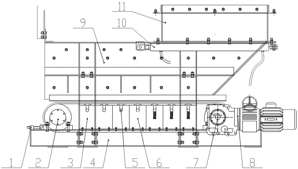
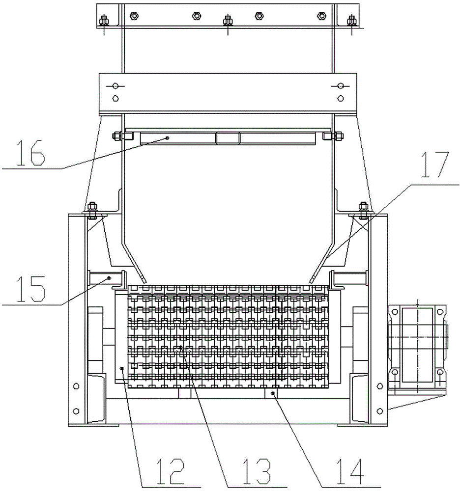
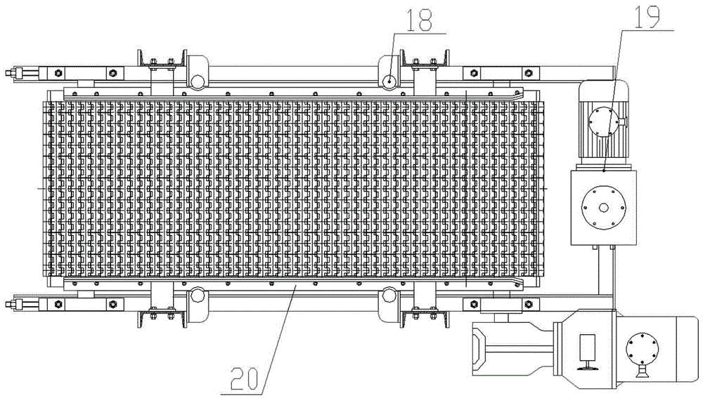
[0024] A belt feeder of the present invention will be described in detail below in conjunction with the accompanying drawings.

[0025] as attached figure 1 , figure 2 , image 3 As shown, a belt feeder is now provided, including a body and a power transmission mechanism. The body includes a chassis 4, a tank body 9 with a gate 16 and a discharge port at the bottom, and a funnel 11. The funnel 11 is installed on the top of the tank body 9 and an electro-hydraulic push rod 10 is arranged at its connection. The tank body 9 is connected and fixed with the underframe 4 through the outrigger 3. The above-mentioned power transmission mechanism is arranged between the tank body 9 and the underframe 4 and connected with The bottom of the tank body 9 is connected, and the power transmission mechanism includes a conveyor belt that is correspondingly arranged at the bottom of the tank body 9. The conveyor belt is closed and installed between the driving drum 7 and the redirecting drum...


PUM


Abstract

The invention provides a belt feeder, which includes a machine body and a power transmission mechanism. The machine body includes a bottom frame, a tank body with a gate and a discharge port at the bottom, and a funnel. The funnel is installed on the top of the tank body and The junction is provided with an electro-hydraulic push rod, and the tank body is connected and fixed to the bottom frame through the legs. The above-mentioned power transmission mechanism is arranged between the tank body and the bottom frame and communicates with the bottom of the tank body. The power transmission mechanism includes a corresponding setting The conveyor belt at the bottom of the trough, the conveyor belt is closed and installed between the driving roller and the reversing roller, the driving roller is connected to the drive assembly, and the two sides of the conveyor belt are equipped with anti-deviation devices. The anti-deviation device refers to the limit rollers arranged on both sides of the conveyor belt. Compared with the prior art, this kind of belt feeder has the advantages of small operating power, light weight, large feeding capacity, stable feeding, convenient adjustment, low noise, small maintenance, and strong versatility of parts. , strong practicability and easy promotion.

Description

technical field [0001] The invention relates to the technology of an industrial belt conveyor feeder, in particular to a belt feeder with simple structure, easy processing and strong practicability. Background technique [0002] In the production process of the national economy, the tape feeder has been widely used, especially when it comes to the transportation of bulk, granular, and powdery materials, the transportation and transfer of materials are completed through the conveying of the feeder, but because of the high altitude The falling impact is strong, and the ordinary belt feeder is seriously damaged, which can no longer meet the actual use. [0003] In order to further prolong the service life of the belt feeder, many manufacturers choose to lay a layer of steel armor belt on the belt to resist impact, but the steel armor belt and the lining belt run out of sync and often cause deviation, and the old design is Install a wear-resistant plate at the bottom of the tan...

Claims


Application Information

Patent Timeline
Patent Type & Authority Patents(China)
IPC IPC(8): B65G47/18B65G15/64B65G39/16
Inventor 潘波
Owner 山东心传矿山机电设备有限公司
Why Eureka
Try Eureka