Air jet loom for weaving lint

An air-jet loom and flannelette technology, which is applied to flannelette looms, looms, textiles, and papermaking, can solve the problems of increasing labor intensity, affecting weaving quality, and different trimming widths, so as to improve weaving quality and weaving efficiency , Superior airflow clustering, precise tension control effect

Active Publication Date: 2014-09-03
QINGDAO TIANYI GROUP RED FLAG TEXTILE MACHINERY
View PDF9 Cites 5 Cited by
  • Summary
  • Abstract
  • Description
  • Claims
  • Application Information

AI Technical Summary

Problems solved by technology

[0002] At present, flannelette is mostly woven by shuttle looms, but the speed of shuttle looms is relatively slow, the noise is high, the weaving efficiency is low, the problem of wool board on the cloth surface is unavoidable, and the working environment is poor, and the number of workers who block the car is becoming more and more more and more difficult
The flannelette is composed of upper and lower layers of cloth and the middle pile warp. The requirement for the warp yarn is also changed from the original one warp yarn to two warp yarns. The let-off speed of the pile warp determines the height of the pile. The let-off speed of the cashmere warp needs to be kept constant, and the phenomenon of high and low cashmere cannot occur. Therefore, uniform ground warp tension, accurate cashmere position, and adjustable cashmere height are the basic requirements for weaving fleece. However, the shuttle loom uses mechanical friction. Type let-off technology, that is, to place the cashmere warp beam and the ground warp beam in the let-off device at the same time to complete the let-off movement, but because the warp let-off movement is mechanical friction, there will be uneven let-off and manual tightening during the weaving process. Disadvantages such as inconvenient yarn delivery
Therefore, the textile industry is more and more inclined to use air-jet looms to weave flannelette, but the existing air-jet looms use profiled reeds for beating-up. In the actual beating-up process, due to the existence of weft shrinkage, the edge During the beating-up process, the lower warp yarns rub against the special-shaped reed, and the reed blades that touch the left and right side yarns are gradually worn out, and in severe cases, the reed teeth of the special-shaped reed will be broken, resulting in an increase in weaving costs.
In addition, when flannelette is weaving, the shrinking problem is relatively serious. In order to ensure the quality of the cloth surface, it is necessary to set temples at the weaving mouth to achieve the purpose of propping up the cloth edges to prevent shrinkage. The temples of the existing air-jet looms The gripping force is far below the requirements, resulting in serious side stand defects, quality decline, increased warp and weft, low efficiency, serious cuts on the reed, shortened service life of the reed, and a series of problems. The loom relies on airflow for weft insertion. Since the weft yarn is led from the left end of the loom to the right to form a raw edge, in order to realize the function of supporting the cloth, the cloth edges on both sides are worn with waste edges during weaving to realize the connection between the upper and lower layers. When the waste After the edge is separated from the weaving mouth by a certain distance to complete the cloth support function, the waste edge is cut off with scissors. This method of edge trimming not only increases the labor intensity of the operator, but also the width of the edge trimming is different, which affects the weaving quality.

Method used


Image

  • Air jet loom for weaving lint
  • Air jet loom for weaving lint
  • Air jet loom for weaving lint

Examples


Embodiment Construction

[0034] The present invention will be further described in detail below in conjunction with the accompanying drawings and specific embodiments, but the present invention is not limited to these embodiments.

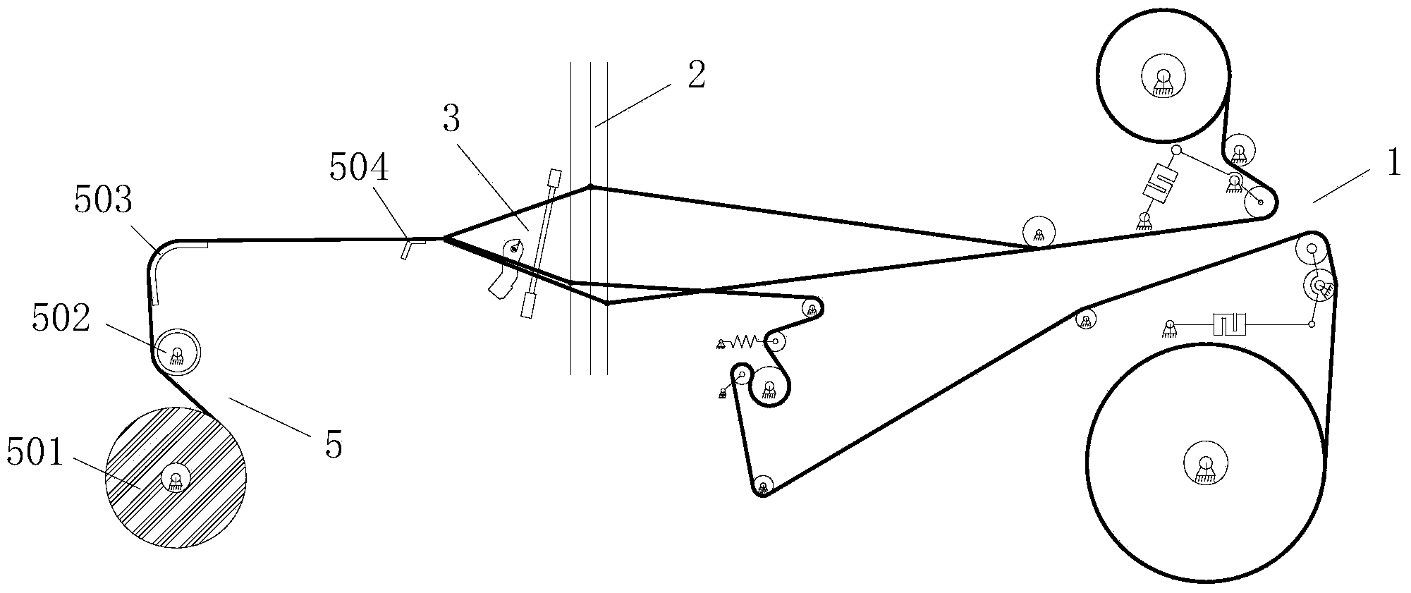
[0035] Such as figure 1 As shown, an air-jet loom for weaving flannelette includes a frame and a control system. A warp let-off device 1, a shedding device 2, a weft insertion device 3 and a take-up device 5 are sequentially arranged on the frame along the weaving direction of the flannelette. Between the coiling device 5 and the weft insertion device 3, a flannelette edge pressing device 4 is arranged.

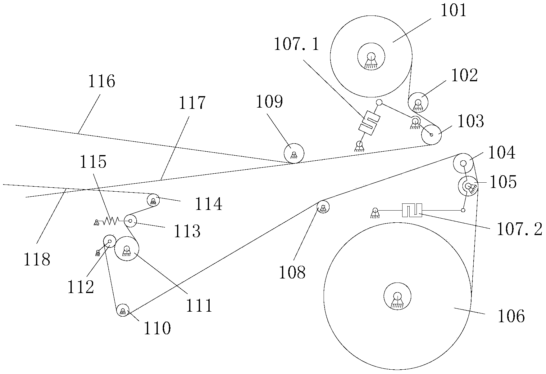
[0036] Such as figure 1 and figure 2 As shown, the let-off device 1 includes a ground warp let-off mechanism arranged on the upper part of the frame and a pile warp let-off mechanism arranged on the lower part of the frame, and the ground warp let-off mechanism is sequentially provided with ground warp let-off mechanisms along the ground warp conveying direction. Warp...


PUM


Abstract

The invention discloses an air jet loom for weaving lint. The air jet loom comprises a frame and a control system, wherein the frame is provided with a warp feeding device, an opening device, a weft guiding device and a coiling device in sequence in a lint weaving direction; the warp feeding device comprises a ground warp feeding mechanism and a pile warp feeding mechanism; the weft guiding device comprises a plurality of pipe piece weft guiding units connected in sequence, and flat reed structures positioned behind the pipe piece weft guiding units; all the pipe piece weft guiding units and the flat reed structures are mounted on a reed base; and a lint edge supporting and ironing device is arranged between the coiling device and the weft guiding device. The air jet loom preferably solves such problems as warp feeding tension control, easy wear of abnormal reeds in a weft guiding process and lint edge shearing encountered in the lint weaving.

Description

technical field [0001] The invention relates to an air-jet loom, in particular to an air-jet loom for weaving fleece. Background technique [0002] At present, flannelette is mostly woven by shuttle looms, but the speed of shuttle looms is relatively slow, the noise is high, the weaving efficiency is low, the problem of wool board on the cloth surface is unavoidable, and the working environment is poor, and the number of workers who block the car is becoming more and more more and more difficult. The flannelette is composed of upper and lower layers of cloth and the middle pile warp. The requirement for the warp yarn is also changed from the original one warp yarn to two warp yarns. The let-off speed of the pile warp determines the height of the pile. The let-off speed of the cashmere warp needs to be kept constant, and the phenomenon of high and low cashmere cannot occur. Therefore, uniform ground warp tension, accurate cashmere position, and adjustable cashmere height are...

Claims


Application Information

Patent Timeline
Patent Type & Authority Applications(China)
IPC IPC(8): D03D47/30D03D39/00D03D47/40D03D49/60D03D49/06
CPCD03D47/278
Inventor 高玉刚赵付斌范龙霄张树杰
Owner QINGDAO TIANYI GROUP RED FLAG TEXTILE MACHINERY
Why Eureka
Try Eureka