Supercharge Your Innovation With Domain-Expert AI Agents!

Self-circulation pressure reduction mechanical seal structure

A mechanical seal, self-circulating technology, used in mechanical equipment, machines/engines, liquid fuel engines, etc., can solve the problems of static ring wear, high seal chamber pressure, high seal chamber pressure, etc., to improve the life of mechanical seals and bearings. , The effect of less liquid leakage and lower pressure value

Inactive Publication Date: 2014-09-03
ANHUI LINE ELECTRIC PUMP
View PDF6 Cites 2 Cited by
  • Summary
  • Abstract
  • Description
  • Claims
  • Application Information

AI Technical Summary

Problems solved by technology

At present, general mechanical seals are prone to high pressure in the seal chamber during work, resulting in excessive wear of the dynamic and static rings of the mechanical seal, resulting in failure of the mechanical seal
At the same time, if the pressure in the sealing chamber is too high, it is easy to cause leakage on the end face.

Method used


Image

  • Self-circulation pressure reduction mechanical seal structure

Examples


Embodiment Construction

[0015] In order to make the technical means, creative features, goals and effects achieved by the present invention easy to understand, the present invention will be further described below in conjunction with specific illustrations.

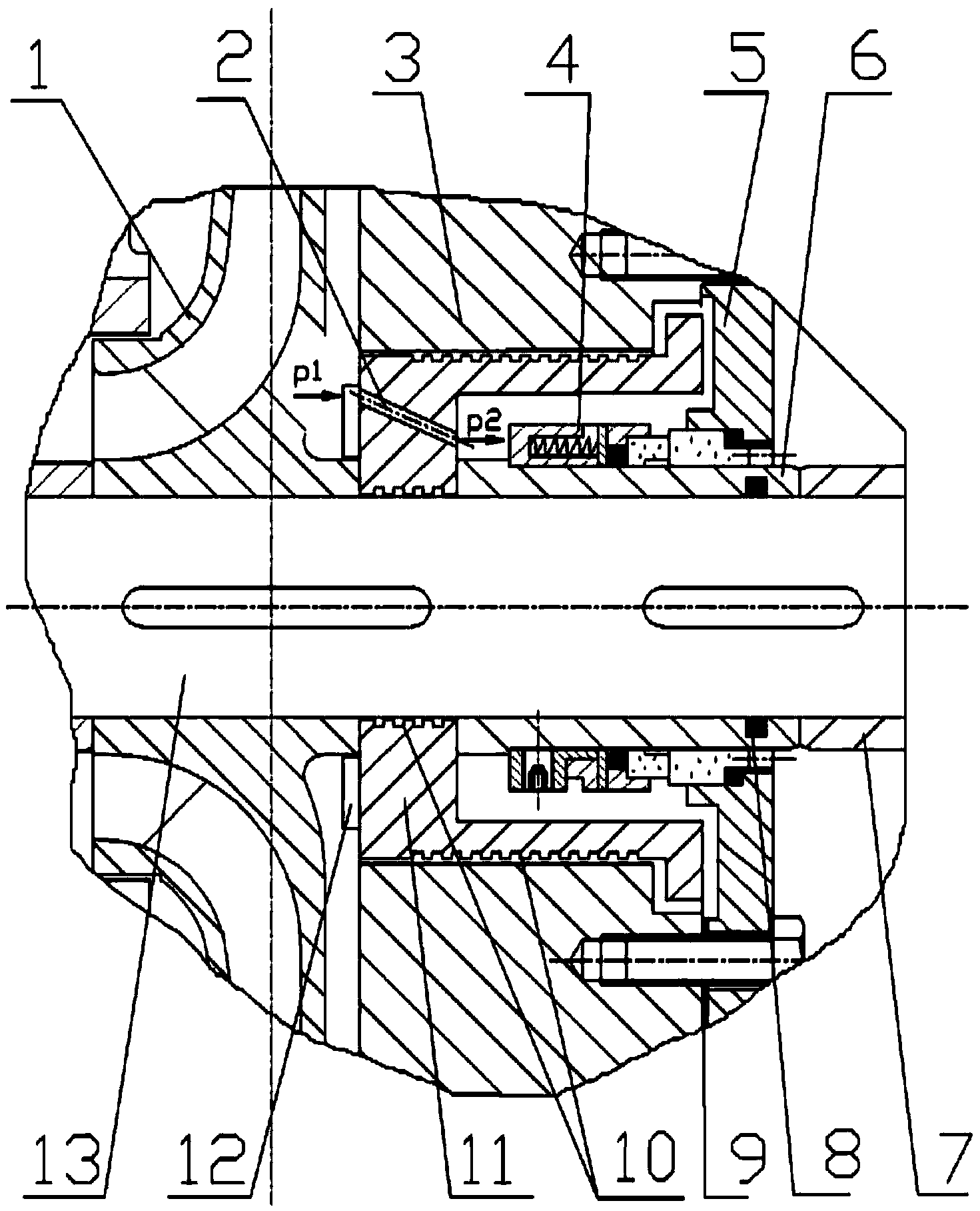
[0016] Such as figure 1 As shown, the mechanical seal structure of the self-circulating decompression device includes a pump shaft 13, an impeller 1 is provided on the left side of the pump shaft 13, a floating pump cover 11 is provided on the right side of the impeller 1, and auxiliary blades 12 are provided on the left side of the floating gland 11. Between the impeller 1 and the floating pump cover 11 is a high-pressure sealing chamber, the floating pump cover 11 is provided with a pump body 3, the right side of the floating pump cover 11 is provided with a mechanical seal bushing 6, and the periphery of the mechanical seal bushing 6 is provided with a mechanical seal 4, A low-pressure sealing cavity is formed between the floating pump cover ...


PUM


Abstract

The invention relates to a self-circulation pressure reduction mechanical seal structure which comprises a pump shaft. An impeller is arranged on the left side of the pump shaft. A floating pump cover is arranged on the right side of the impeller. A mechanical seal is arranged in an inner cavity of the floating pump cover. A high-pressure seal cavity is formed between the impeller and the floating pump cover. A low-pressure seal cavity is formed inside the floating pump cover. A through hole connecting the high-pressure seal cavity with the low-pressure seal cavity is formed in the floating pump cover. A rectangular spiral water tank is arranged on the outer circle of the floating pump cover. Auxiliary blades are arranged on the side, close to the impeller, of the floating pump cover. The stressed area of the floating pump cover in an impeller high-pressure zone is smaller than the stressed area in the horizontal direction of the floating pump cover. A rotary shaft grooving type water seal is formed by the rectangular spiral water tank. A gap between water seal assemblies is filled with seal liquid. An O-shaped seal ring is arranged between a mechanical seal gland and a mechanical seal shaft sleeve. The self-circulation pressure reduction mechanical seal structure has the advantages that the pressure values of the seal cavities, axial force and liquid leakage can be reduced, the service life of the mechanical seal and a bearing is prolonged, and therefore the service life of a water pump is prolonged.

Description

technical field [0001] The invention relates to the technical field of mechanical seals, in particular to a self-circulating pressure-reducing mechanical seal structure. Background technique [0002] A mechanical seal refers to a structure that prevents fluid leakage by at least a pair of end faces perpendicular to the axis of rotation, under the action of fluid pressure and the elastic force (or magnetic force) of the compensation mechanism, and the cooperation of auxiliary seals to keep fit and slide relative to each other. At present, general mechanical seals are prone to high pressure in the sealing chamber during operation, resulting in excessive wear of the dynamic and static rings of the mechanical seal, resulting in failure of the mechanical seal. At the same time, if the pressure in the sealing chamber is too high, it is easy to cause leakage on the end face. Contents of the invention [0003] The technical problem to be solved by the present invention is to prov...

Claims


Application Information

Patent Timeline
Patent Type & Authority Applications(China)
IPC IPC(8): F04D29/16F04D29/12
Inventor 程茂胜李圣宁
Owner ANHUI LINE ELECTRIC PUMP
Features
  • R&D
  • Intellectual Property
  • Life Sciences
  • Materials
  • Tech Scout
  • Unparalleled Data Quality
  • Higher Quality Content
  • 60% Fewer Hallucinations
Learn More