Heat sensor with driving function

A thermal sensor and functional technology, applied in the field of thermal sensors with driving function, can solve the problems of thermocouples not resistant to flame ablation, hidden dangers, potential difference, etc.

Inactive Publication Date: 2014-09-03
李仲伦
View PDF4 Cites 2 Cited by
  • Summary
  • Abstract
  • Description
  • Claims
  • Application Information

AI Technical Summary

Problems solved by technology

The thermocouple is made of two kinds of metals. Due to the different heat conduction conditions and different molecular chain structures, a potential difference will be generated when the flame is heated. The current generated by the potential difference is used as the power s

Method used


Image

  • Heat sensor with driving function
  • Heat sensor with driving function
  • Heat sensor with driving function

Examples


Embodiment Construction

[0034] A thermal sensor with driving function of the present invention will be described in detail below with reference to the embodiments and the accompanying drawings.

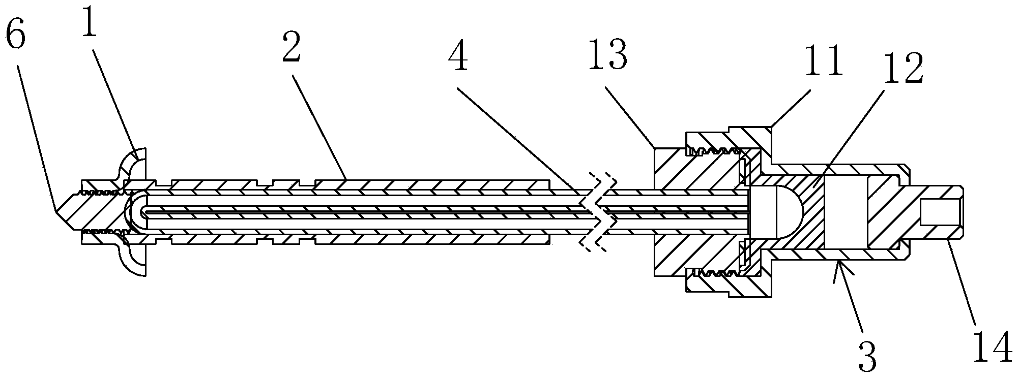
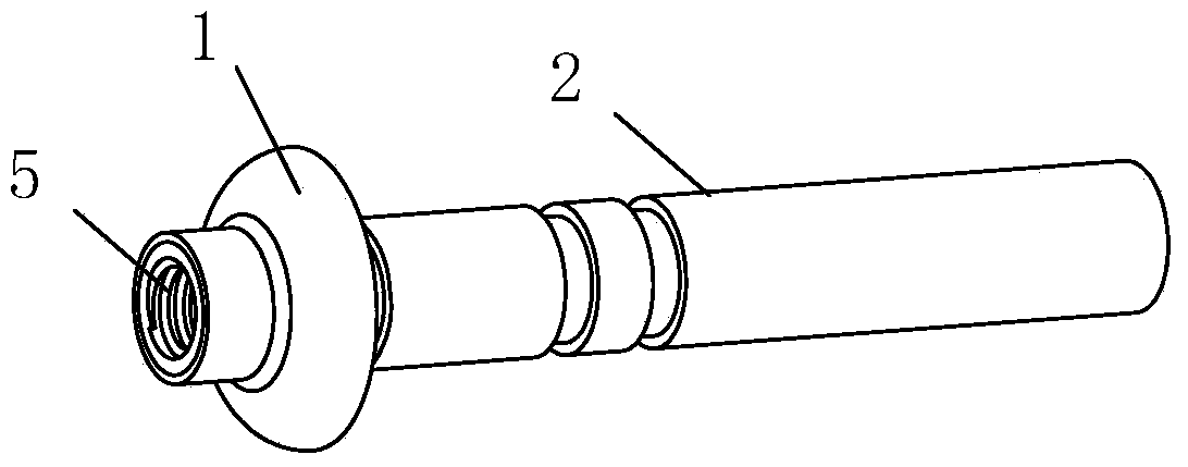
[0035] like figure 1 , image 3 As shown, a thermal sensor with driving function of the present invention includes: one end is provided with a sleeve cap 1 and the other end is an open sleeve 2, a driving cylinder 3, and one end from the open end of the sleeve 2 Inserted into the sleeve 2, the other end is connected to the U-shaped pipe 4 of the cylinder 3, the center of the sleeve cap 1 is formed with a sleeve internal thread 5 penetrating with the sleeve 2, and the sleeve cap 1 passes through the The sleeve internal thread 5 described above is connected with a heat collecting needle 6 for absorbing heat source.

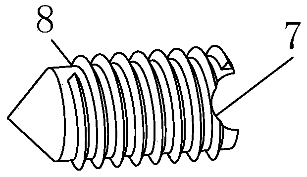
[0036] like figure 2 As shown, one end of the heat collecting needle 6 is a tapered structure, and the other end is formed with a heat collecting needle inner arc 7 for combining with the end ...


PUM


Abstract

Provided is a heat sensor with a driving function. The heat sensor is provided with a sleeve, an air cylinder for driving and a U-shaped tube. One end of the sleeve is provided with a sleeve cap, and the other end of the sleeve is open; one end of the U-shaped tube is inserted into the sleeve from the open end of the sleeve, and the other end of the U-shaped tube is connected with the air cylinder; sleeve inner threads running through the sleeve are formed in the center of the sleeve cap, and the sleeve cap is connected with a heat collection needle through the sleeve inner threads, wherein the heat collection needle is used for absorbing heat sources. The air cylinder is provided with a two-hole screw arranged at one end of a longitudinally through air cylinder body and used for being inserted into the two open ends of the U-shaped tube, a rubber sealing cap arranged in the air cylinder body and combined with the two-hole screw tightly and a T-shaped tubular piston arranged at the other end of the air cylinder body, and the T-shaped tubular piston can stretch out to be used for driving an external part to move when the rubber sealing cap is heated to expand. Thermal cycle power can be generated after the inner portion of the heat sensor is under the high temperature, power is conveyed to a control switch repeatedly and continuously, and the heat sensor cannot be damaged because of flame ablation, and is reliable and durable.

Description

technical field [0001] The invention relates to a thermal sensor. In particular, it relates to a thermal sensor with drive function. Background technique [0002] In the prior art both at home and abroad, the sensors used for the gas leakage prevention device of the burning appliance all adopt thermocouples as control switches. The thermocouple is made of two kinds of metals. Due to the different heat conduction conditions and different molecular chain structures, a potential difference will be generated when the flame is heated. The current generated by the potential difference is used as the power source of the control switch, but the thermocouple is not resistant to flame ablation. Once the metal chain structure is destroyed after ablation, the function of the control switch will be lost, and there will be no obvious response, so there are still potential hidden dangers. In order to avoid this potential hidden danger, it is urgent to choose other solutions to avoid the ...

Claims


Application Information

Patent Timeline
IPC IPC(8): G01D5/42
Inventor 李仲伦解达
Owner 李仲伦
Why Eureka
Try Eureka