Automobile meter indicator lamp color detecting method based on dynamic clustering method

A technology for color detection and automotive instrumentation, applied in the direction of color measurement devices, etc., can solve the problems of unreasonable detection algorithm, high false detection rate, low reliability and accuracy of detection results, etc., to ensure friendliness and robustness, improve Reliability, the effect of improving reliability and accuracy

Active Publication Date: 2014-09-03
HARBIN INST OF TECH
View PDF4 Cites 3 Cited by
  • Summary
  • Abstract
  • Description
  • Claims
  • Application Information

AI Technical Summary

Problems solved by technology

[0005] The purpose of the present invention is to propose a method for detecting the color of an automotive instrument indicator light based on a dynamic clustering method, so as to solve the problem of

Method used


Image

  • Automobile meter indicator lamp color detecting method based on dynamic clustering method
  • Automobile meter indicator lamp color detecting method based on dynamic clustering method
  • Automobile meter indicator lamp color detecting method based on dynamic clustering method

Examples


Example Embodiment

[0036] Embodiment 1: A method for detecting the color of an automobile instrument indicator light based on a dynamic clustering method described in this embodiment includes the following steps:

[0037] Step 1. Clustering of indicator colors, the specific process is as follows:

[0038] Step 11. Select N qualified vehicle instrument indicator lights as initial samples, use the camera to obtain the image of the instrument indicator light when it is working, and perform color statistical analysis on the indicator light pixels, so as to obtain the RGB value of the indicator light, and place the indicator light in RGB. The value in the color space is converted into the value in the HSL space;

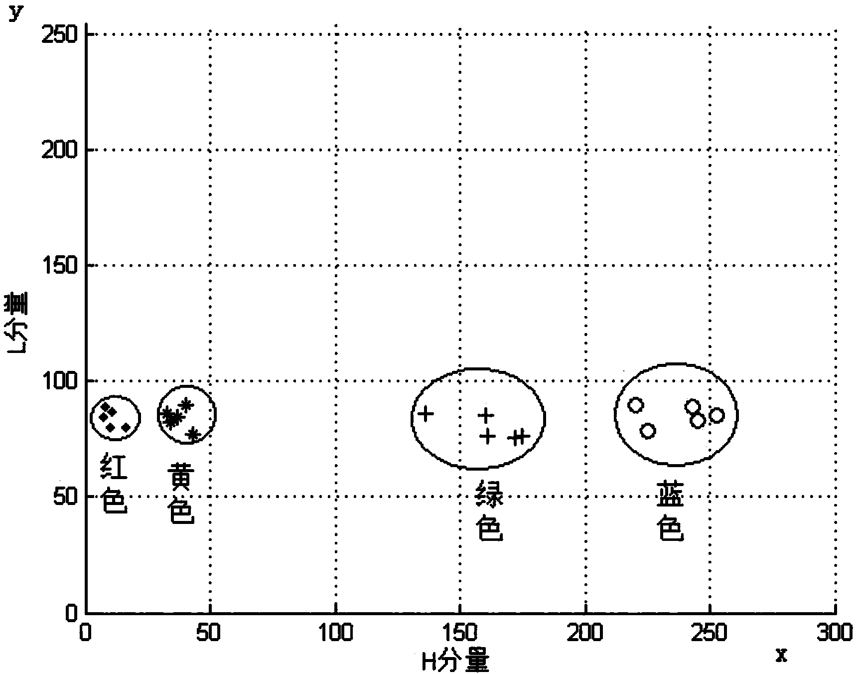
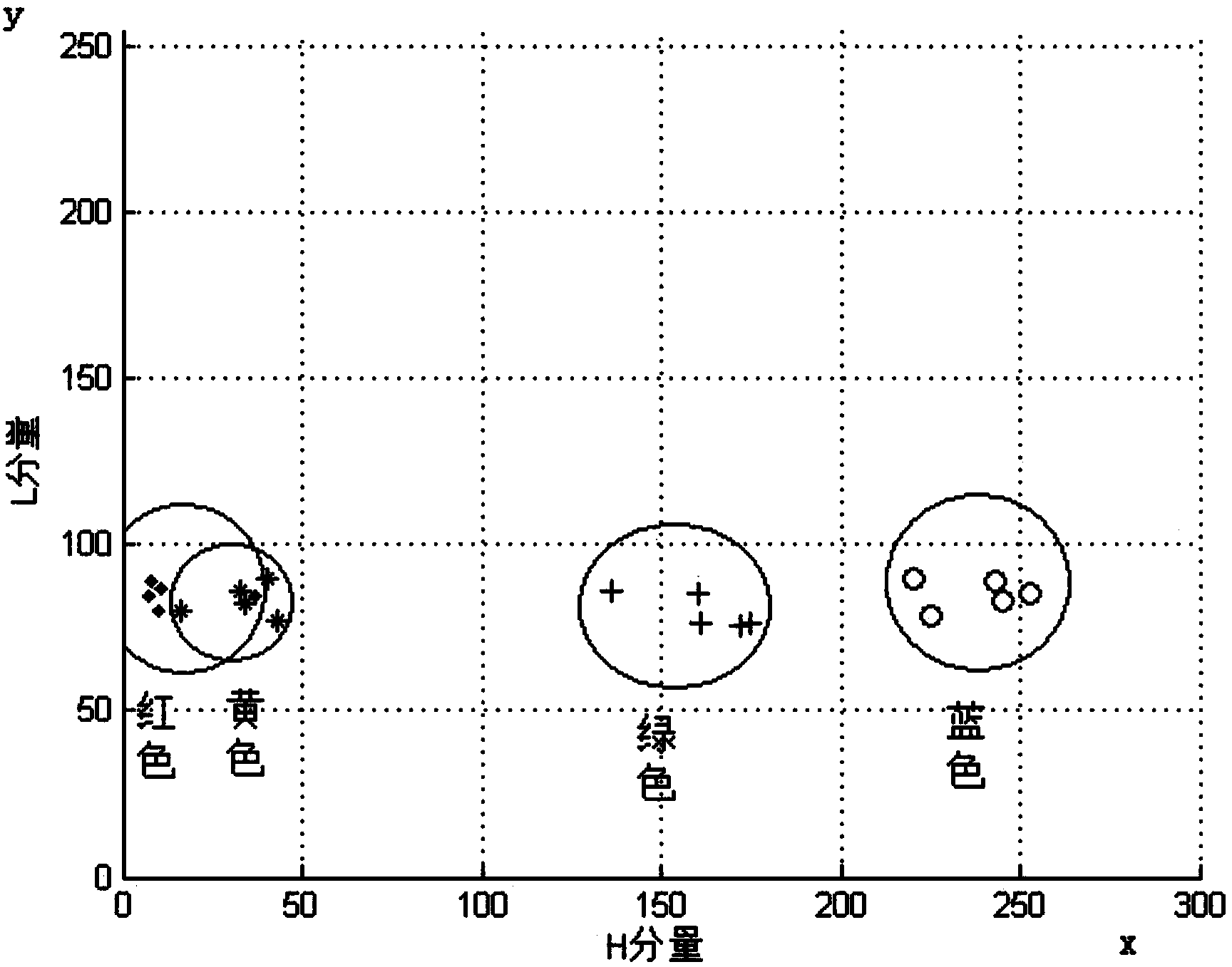
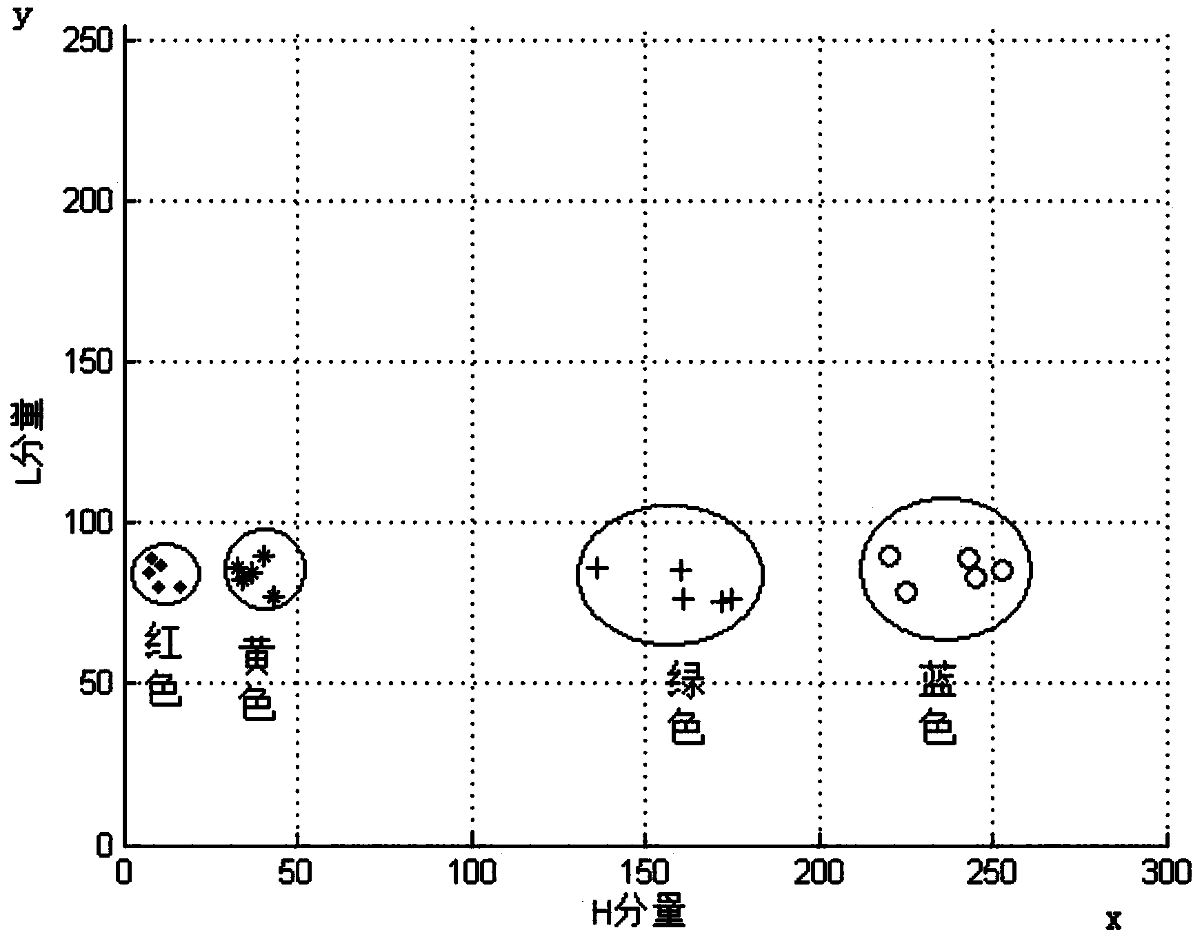
[0039] Steps 1 and 2: Classify the sample indicator lights by color, specifically: take the H component of the indicator light as the x-axis, the L component as the y-axis, and use z=(x, y) to represent the color value of the indicator light; according to the color of the indicator light T...

Example Embodiment

[0054] Embodiment 2: The difference between this embodiment and Embodiment 1 is that the processing method described in step 16 is as follows:

[0055] Compare the final classification of the indicator samples with the initial classification of the indicator samples. If they are inconsistent, the indicator samples are wrong, and find and print the wrong indicator samples; if they are consistent, the indicator samples are correct and the classification is reasonable, and the clustering method will be used. The information is stored in the database as a clustering standard for detecting the color of the indicator light. Other steps and parameters are the same as in the first embodiment.

Example Embodiment

[0056] Embodiment 3: The difference between this embodiment and Embodiment 1 or 2 is that the classification method described in Step 2 and 2 is as follows:

[0057] Use the camera to obtain the image of the new indicator R of the meter, perform color statistical analysis on the pixels of the indicator, so as to obtain the RGB value of the indicator, convert the value of the indicator in the RGB color space into the value in the HSL space, and use the indicator to calculate the value of the indicator. The H component is the x-axis, and the L component is the y-axis. Use z=(x, y) to represent the color value of the indicator light, and set R at Γ i middle.

[0058] Other steps and parameters are the same as in the first or second embodiment.


PUM


Abstract

The invention belongs to the technical field of detection on automobile meter indicator lamp colors, and provides an automobile meter indicator lamp color detecting method based on a dynamic clustering method. The automobile meter indicator lamp color detecting method based on the dynamic clustering method solves the problems that an existing automobile meter indicator lamp color detecting method is high in false detection rate, not reasonable in detecting algorithm, and low in reliability and accuracy of detecting results. The method includes the two steps of clustering of the indicator lamp colors and detection on the indicator lamp colors. The automobile meter indicator lamp color detecting method based on the dynamic clustering method is applicable to the detection on the automobile meter indicator lamp colors.

Description

technical field [0001] The invention relates to a method for detecting the color of an automobile instrument indicator light based on a dynamic clustering method, and belongs to the technical field of color detection of an automobile instrument indicator light. Background technique [0002] Automobile instrument manufacturers will purchase various colors of LED lights for the display of automobile instrument indicators. In the assembly line production of instruments, there are cases where LED lights are installed incorrectly due to worker errors. Therefore, in the automatic detection of automobile instruments, LED lights are used. detection is essential. The detection of LED lights needs to detect error conditions such as continuous lamps, wrong lamp color, and wrong lamp shape. In these error conditions, there is no reasonable and reliable detection algorithm for the detection of lamp color errors. [0003] In the traditional color matching algorithm, it is often judged ac...

Claims


Application Information

Patent Timeline
IPC IPC(8): G01J3/46
Inventor 高会军华枭于金泳由嘉
Owner HARBIN INST OF TECH
Why Eureka
Try Eureka