Online gas pressure-tapping method and online gas pressure-tapping device

A technology of gas and gas pipelines, which is applied in the direction of measuring devices, measuring fluid pressure, instruments, etc., can solve problems such as damage, no isolation measures, and large fluctuations in pressure data, so as to achieve accurate and reliable equipment operation, equipment intrinsically safe, and data The realism-enhancing effect of

Inactive Publication Date: 2014-09-03
JIGANG GRP
View PDF10 Cites 5 Cited by
  • Summary
  • Abstract
  • Description
  • Claims
  • Application Information

AI Technical Summary

Problems solved by technology

[0005] 1. The efficiency is low. Every time the zero point of the pressure measurement unit is adjusted, the signal line and the transmission unit need to be removed. It is very easy to damage the equipment and then restore the original state. The operation process is complicated and the efficiency is low. It takes about an hour
[0006] 2. It is difficult to dredge the pressure-taking pipeline, and the dirty medium will often block the pressure-taking pipeline, thereby affecting pressure measurement and flow measurement. When the pipeline needs to be dredged, all parts above the ball valve need to be disassembled and then reinstalled
[0007] 3. The failure rate of the measuring element is high. When measuring the pressure of corrosive media, this installation method does not have the necessary isolation measures, and the membrane box of the equipment is easily corroded, resulting in damage
[0008] 4. Insufficient safety, the measuring element is in direct contact with flammable and explosive media. From the perspective of intrinsic safety, this installation method needs to be improved
[0009] 5. The measured pressure data fluctuates greatly, because there is no necessary buffer part, any change in the pipeline will be reflected in the pressure measurement value

Method used


Image

  • Online gas pressure-tapping method and online gas pressure-tapping device
  • Online gas pressure-tapping method and online gas pressure-tapping device
  • Online gas pressure-tapping method and online gas pressure-tapping device

Examples


Embodiment Construction

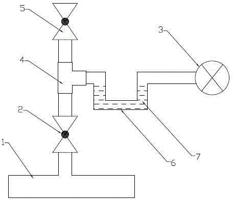
[0033] Such as figure 2 A kind of gas online pressure taking method of the present invention shown, comprises the following steps:

[0034] 1) Installation process: Open a hole in the appropriate position of the gas pipeline, the size of the hole is between 17mm-20mm, weld a D15 pipe fitting with wire at one end, and install the main ball valve 2 (Q11F-16C, DN15mm) at the other end with the wire, after the main ball valve 2 Connect the D15 paired wire fittings, install D15 tee 4 after the paired wire fittings, and then connect the D15 paired wire fittings to the vertical port of the tee 4, install D15 auxiliary ball valve 5 after aligning the wire fittings, and connect the horizontal port of the tee 4 to a U-shaped pipe with a diameter of 15mm After the pipeline 6 and the U-shaped pipeline are filled with the spacer fluid 7, the pressure transmitter 3 is installed.

[0035] Among them, the U-shaped pipeline 6 is made of seamless steel pipe or copper pipe; when filling the sp...


PUM


Abstract

The invention provides an online gas pressure-tapping method and an online gas pressure-tapping device. The method comprises the steps of (1) mounting the pressure-tapping device, (2) resetting the device, and (3) carrying out gas pressure-tapping. The device comprises a main ball valve, a pressure transmitter, a tee joint, an auxiliary ball valve and a U-shaped pipeline; one end of the main ball valve is communicated with a gas pipeline by use of a pressure-tapping pipeline, while the other end of the main ball valve is connected with a lower opening of a three-way joint by use of a pipeline; the auxiliary ball valve is connected with an upper opening of the three-way joint by use of a pipeline; one end of the U-shaped pipeline is connected with a right opening of the three-way joint, while the other end of the U-shaped pipeline is connected with the pressure transmitter. The online gas pressure-tapping method and the online gas pressure-tapping device have the advantages that the traditional mounting manner is broken through, the working efficiency is improved, necessary isolation measure is carried out, the pressure-tapping pipeline is convenient to dredge, and the safety and accuracy are greatly improved.

Description

technical field [0001] The invention relates to a pressure acquisition technology for energy flow metering (gas medium) compensation, in particular to a gas online pressure acquisition method and device. Background technique [0002] When measuring energy flow, when the temperature and pressure change, the density of the measured medium will change accordingly, resulting in measurement errors in the flowmeter. In order to reduce the error, temperature and pressure compensation can be adopted to reduce the measurement error. The essence of the so-called temperature and pressure compensation is the density correction measures taken when the temperature and pressure of the medium are inconsistent with the values ​​adopted in the design. [0003] The pressure compensation of the medium has a large proportion in the flow measurement. directly affect the accuracy of the measurement results. [0004] At present, the straight-through pressure measurement method is mainly used (se...

Claims


Application Information

Patent Timeline
Patent Type & Authority Applications(China)
IPC IPC(8): G01L19/00G01L19/06
Inventor 王波李鹏立王玉弟张德华张继广
Owner JIGANG GRP
Why Eureka
Try Eureka