Reliability loading testing device and method for main shaft of numerically controlled lathe

A loading test device, loading device technology, applied in the direction of measuring devices, testing of mechanical components, testing of machine/structural components, etc., can solve the problems of lack of testing of spindle precision decline, easy loss of precision, spindle loading, etc., to achieve improvement Test efficiency and fault acquisition speed, scientific test method, high efficiency effect

Inactive Publication Date: 2014-09-03
通用技术集团沈阳机床有限责任公司
View PDF7 Cites 39 Cited by
  • Summary
  • Abstract
  • Description
  • Claims
  • Application Information

AI Technical Summary

Problems solved by technology

Moreover, due to the high-speed movement of the spindle, the precision is easily lost in the cutting state
Domestic reliability tests on CNC machine tool spindles started relatively late. At present, the reliability tests on spindles are mainly carried out on machine

Method used


Image

  • Reliability loading testing device and method for main shaft of numerically controlled lathe
  • Reliability loading testing device and method for main shaft of numerically controlled lathe
  • Reliability loading testing device and method for main shaft of numerically controlled lathe

Examples


Embodiment 1

[0034] Example 1 A Reliability Loading Test Device for CNC Lathe Spindle

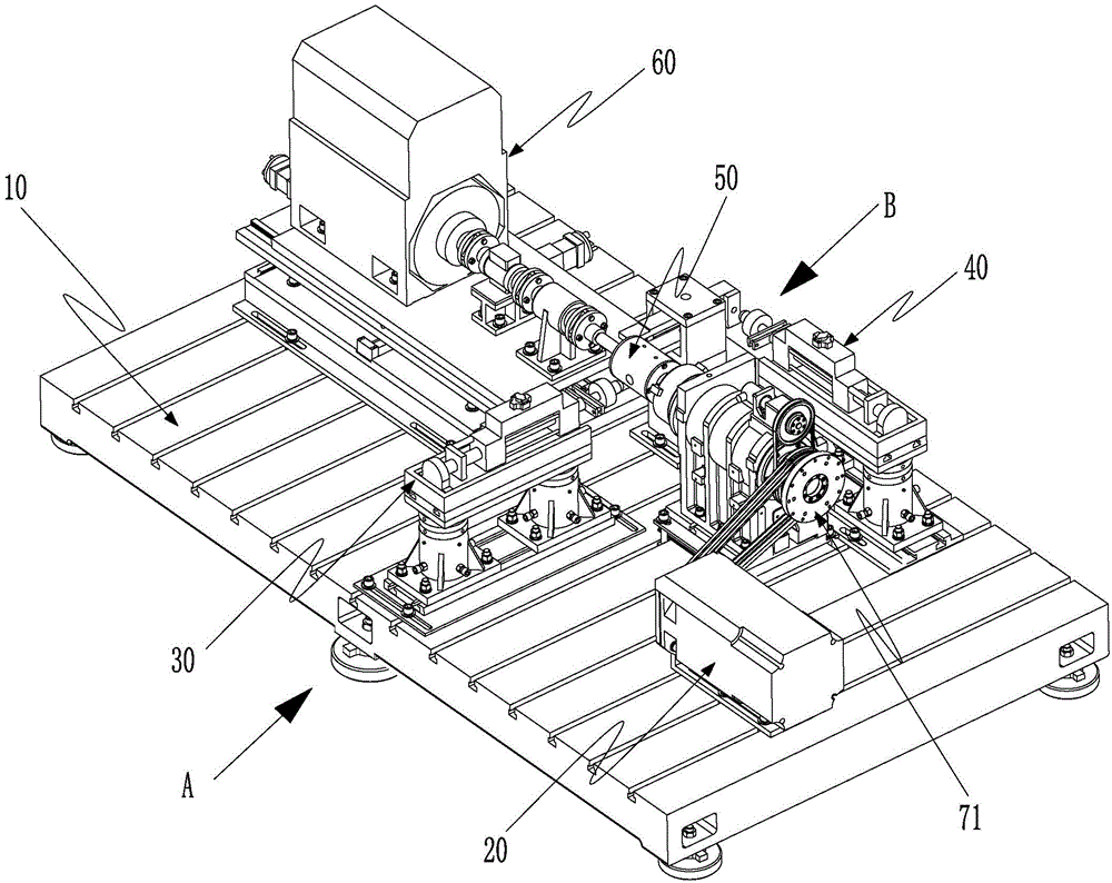
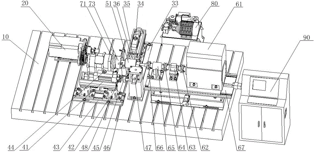
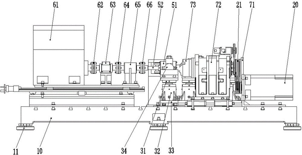
[0035] Such as Figure 1-Figure 6 As shown, a CNC lathe spindle reliability loading test device consists of a test bench body (10), a motor (20), a radial cutting force simulation loading device (30), an axial cutting force simulation loading device (40), a bearing It consists of a loading unit (50), a torque loading system (60), a hydraulic system (80) and a control system (90).

[0036] The motor (20), radial cutting force simulation loading device (30), axial cutting force simulation loading device (40), bearing loading unit (50) and torque loading system (60) are installed on the test bench body (10).

[0037] The test bench body (10) is installed on the ground through a vibration damping pad (11). Before carrying out the test, the table top of the test bench body is made level by adjusting the damping pad (11) at the bottom of the test bench body (10). Preferably, several T-slots for fixing are ...

Embodiment 2

[0046] Example 2 A reliability loading test method for the spindle of a CNC lathe

[0047] Adopt the test device of embodiment 1, method is as follows:

[0048] 1) Measure the radial and axial rotation accuracy of the initial state of the tested main shaft (71) with a dial indicator, and measure the static stiffness of the initial state of the tested main shaft;

[0049] 2) The tested spindle (71) is fixed on the test bench body (10) through the spindle box (72), the motor (20) drives the tested spindle to run through the belt (21), and the tested spindle is continuously idling for 72 hours. Stop once every 24 hours to test the rotation accuracy and static stiffness of the tested spindle;

[0050] 3) Carry out a 24h loading test on the tested spindle (71):

[0051] The torque loading system (60) applies torque loading to the measured main shaft through the bearing loading unit (50).

[0052] The radial cutting force simulation loading device (30) applies a radial simulation...


PUM


Abstract

The invention relates to a reliability loading testing device and a reliability loading testing method for a main shaft of a numerically controlled lathe. The testing device comprises a testing platform body and a control system, wherein the testing platform body is provided with a motor, a radial cutting force simulated loading device, an axial cutting force simulated loading device, a bearing loading unit and a torque loading system. The main shaft to be detected is fixedly arranged on the testing platform body through a main shaft box . The motor drives the main shaft to be detected by a belt; the radial cutting force simulated loading device, the axial cutting force simulated loading device and the torque loading system are used for applying a torque, a radial force and an axial force to the main shaft to be detected through the bearing loading unit. The invention creates a condition for simulating the main shaft under a cutting state of the lathe; a reliability loading test and a precision recession test on the main shaft of the numerically controlled lathe can be realized; an early-stage fault of the main shaft is exposed and a precision recession rule of the main shaft is grasped.

Description

technical field [0001] The invention relates to the field of machine tool spindle testing, in particular to a reliability loading test device and method for a CNC lathe spindle. Background technique [0002] As the main motion system of CNC machine tools, the spindle is one of the most important functional components of CNC machine tools. The reliability of the machine tool depends largely on the spindle system, whose failures occur frequently and are highly harmful. Moreover, due to the high-speed movement of the spindle, the precision is easily lost in the cutting state. Domestic reliability tests on CNC machine tool spindles started relatively late. At present, the reliability tests on spindles are mainly carried out on machine tools, and only simple continuous dry-running tests and temperature rise tests can be carried out. It is impossible to simulate dynamic cutting force on the spindle. In the case of loading, the test for the deterioration of the spindle accuracy i...

Claims


Application Information

Patent Timeline
IPC IPC(8): G01M13/00
Inventor 刘阔李焱宋威李洪涛谭智吴玉亮
Owner 通用技术集团沈阳机床有限责任公司
Why Eureka
Try Eureka