Mechanical type stress-corrosion coupling fatigue test device

A fatigue test, mechanical technology, applied in the direction of measuring devices, weather resistance/light resistance/corrosion resistance, machine/structural component testing, etc., can solve the problem of difficult control of temperature environment, low precision, difficulty in concrete multiaxial fatigue test, etc. problem, to achieve the effect of small test temperature fluctuation and high precision

Inactive Publication Date: 2014-09-03
CHANGAN UNIV
View PDF9 Cites 16 Cited by
  • Summary
  • Abstract
  • Description
  • Claims
  • Application Information

AI Technical Summary

Problems solved by technology

The main reason for less research on concrete multiaxial fatigue tests is that concrete multiaxial fatigue tests are relatively difficult. On the one hand, the development of multiaxial fatigue test systems is difficult and expensive. On the other hand, there are several key points in the test technical problem
[0003] There are also some problems in the mechanical stress-corrosion coupling fatigue test device currently on the market: the test environment is relatively single, it cannot adapt to the test environment of various media, and its temperature environment is also difficult to control, the test temperature fluctuates relatively large, and the accuracy is low

Method used


Image

  • Mechanical type stress-corrosion coupling fatigue test device
  • Mechanical type stress-corrosion coupling fatigue test device

Examples


Embodiment Construction

[0016] In order to make the objects and advantages of the present invention clearer, the present invention will be further described in detail below in conjunction with the examples. It should be understood that the specific embodiments described here are only used to explain the present invention, not to limit the present invention.

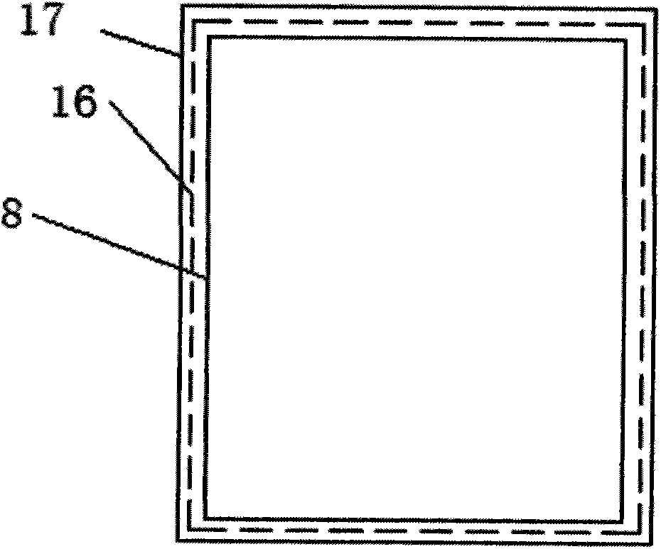
[0017] Such as figure 1 As shown, this specific implementation example provides a mechanical stress-corrosion coupling fatigue test device, including a base 1, a bracket 2, a motor 3, a reducer 4, a connecting rod 5, an indenter 6, a test piece 7 and a sealed corrosion medium Box 8, the base 1 is provided with a support 2, the center of the top of the support 2 is provided with a motor 3, the motor 3 is connected to the connecting rod 5 through a reducer 4, and the end of the connecting rod 5 is provided with a pressure head 6 , the indenter 6 is in contact with the test piece 7, and both the indenter 6 and the test piece 7 are sealed in the se...


PUM


Abstract

The invention discloses a mechanical type stress-corrosion coupling fatigue test device which comprises a base, a bracket, a motor, a speed reducer, a connecting rod, a pressure head, a test piece and a closed corrosion medium box, wherein the bracket is arranged on the base; the motor is arranged at the center of the top of the bracket and is connected with the connecting rod through the speed reducer; the pressure head is arranged on one end part of the connecting rod and is in contact with the test piece; the pressure head and the test piece are closed in the closed corrosion medium box through a cover; the connecting rod penetrates through the cover and is connected with the pressure head; the cover is connected with the closed corrosion medium box through a thread; a hard pipe is arranged at one end on the cover; a valve is arranged on the hard pipe. According to the mechanical type stress-corrosion coupling fatigue test device, the type of corrosion mediums for tests is expanded, and test environments of various mediums can be simulated; the device has temperature and pressure control functions and can execute the test at the temperature of 0-80+ / -2 DEG C; due to a heat preservation system of a box body, the test temperature fluctuation is small, and the precision is high.

Description

technical field [0001] The invention relates to a fatigue test device, in particular to a mechanical stress-corrosion coupling fatigue test device. Background technique [0002] Reinforced concrete structures are usually mainly subjected to static loads, but in actual engineering, there are many structures such as bridges, crane beams, etc., in addition to bearing static loads, fatigue damage occurs due to repeated cyclic loads. The fatigue characteristics of structures are very complex. It is of great significance to the overall safety of structures to accurately identify whether structures or components are damaged, determine the location and degree of damage, and predict their fatigue life. So far, the research on multiaxial fatigue of concrete is not extensive and in-depth. There are only cyclic compression fatigue on one side and the other side, biaxial compression fatigue, triaxial fatigue of cylinder under confining pressure and axial compression, and cylinder fatigue...

Claims


Application Information

Patent Timeline
Patent Type & Authority Applications(China)
IPC IPC(8): G01N3/38G01N17/00G01M99/00
Inventor 刘开平关博文邢明亮从培良孙增智王振军熊锐何锐盛艳萍田耀刚
Owner CHANGAN UNIV
Why Eureka
Try Eureka