
Installation structure and installation method of earthquake electromagnetic disturbance sensor

An electromagnetic disturbance and installation method technology, applied in the direction of electric/magnetic exploration, instruments, measuring devices, etc., can solve the problems of metal-like pipeline interference, weak anti-interference ability, and inability to directly detect changes in the earth's magnetic field, and achieve easy Achievement and low cost effect

Active Publication Date: 2014-09-03
郑州晶微电子科技有限公司
View PDF6 Cites 5 Cited by
  • Summary
  • Abstract
  • Description
  • Claims
  • Application Information

AI Technical Summary

Problems solved by technology

[0002] The installation method of seismic electromagnetic instruments currently used is still the installation method adopted by digital geomagnetic field instruments in the mid-1980s. The horizontal installation method used in this installation method is divided into north-south direction and east-west direction. The observation site requirements are relatively large, and an electromagnetic disturbance sensor is required in each direction to measure the magnetic field change in that direction, and the distance between the two electromagnetic disturbance sensors is relatively long; secondly, the sensor is generally buried about 3 meters deep in the horizontal installation mode. , so the sensor can directly measure the changing magnetic field on the earth's surface, but it cannot directly measure the change of the earth's internal magnetic field; in addition, the biggest shortcoming is that the anti-interference ability is relatively weak, and it is vulnerable to such as ultra-high voltage transmission system, rail transit system, large-scale utility Electrical equipment, metal-like pipeline systems, man-made and metal-like pipeline interference that changes the electrical structure of the surface, etc.

Method used


Image

  • Installation structure and installation method of earthquake electromagnetic disturbance sensor
  • Installation structure and installation method of earthquake electromagnetic disturbance sensor
  • Installation structure and installation method of earthquake electromagnetic disturbance sensor

Examples


Embodiment Construction

[0014] The present invention will be further described below in conjunction with accompanying drawing:

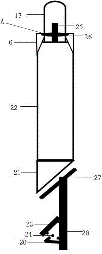
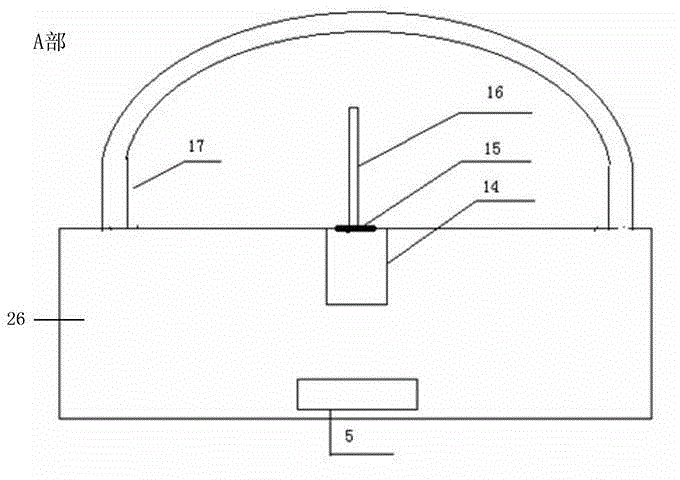
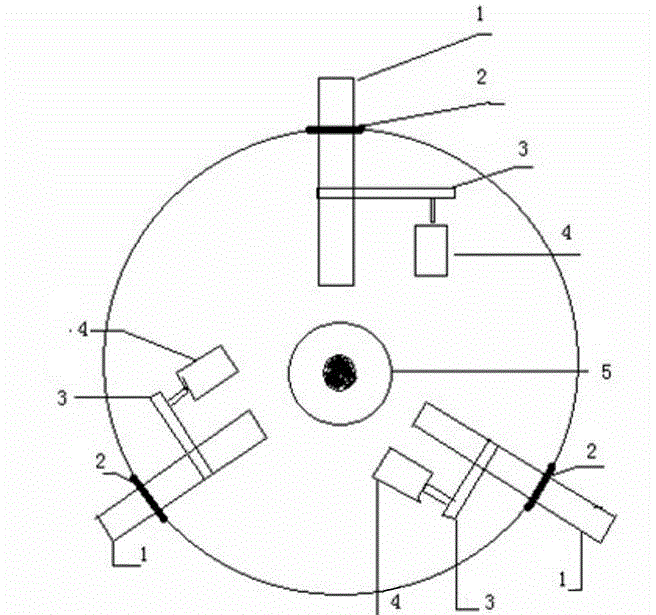
[0015] The installation method of the electromagnetic disturbance sensor is to drill an observation well at the observation station, the diameter of which is greater than 50mm, and the inclination of the drilling hole is less than 5 degrees. The observation well is equipped with a non-magnetic casing, and the electromagnetic disturbance sensor 22 is vertically installed at a suitable position within a depth of 1000m. , the electromagnetic disturbance sensor 22 sends the induced signal to the magnetic signal processor through the signal for amplification, filtering and other related processing, and the signal line passes through the PVC pipe for fixing and protection. A metal lifting ring 17 is fixed on the top of the sensor, which is used to lower the sensor into the well, and the signal monitored by the sensor is sent to the ground equipment through the signal cable, and a ...


PUM


Abstract

The invention provides an installation structure and installation method of an earthquake electromagnetic disturbance sensor. According to the method, a deep well is adopted for installation, an observation well is dug in an observation station, the inclination of the well is smaller than 5 degrees, a totally closed metal or nonmetal magnetic-free casing pipe is adopted, the electromagnetic disturbance sensor is vertically installed at the proper position within 1000 meters of the well depth, a locating base used for supporting the gravity of the electromagnetic disturbance sensor and a horizontal adjusting device used for adjusting the electromagnetic disturbance sensor to keep horizontal are arranged, a swinging ring is fixed to the top of the sensor and used for placing the sensor into the well and fixing the sensor, signals monitored by the sensor are sent to ground equipment through a signal cable, a cement well table is built at a well mouth, and a cement cover is additionally arranged for protection. According to the installation structure and installation method of the earthquake electromagnetic disturbance sensor, the structure is simple, implementation is easy, cost is low, and the floor space is small; interference of a high-voltage power transmission system, a rail transit system, large electric equipment, a metalloid pipeline system and a metalloid pipeline changing a surface electrical property structure, man-made interference and the like can be avoided effectively.

Description

technical field [0001] The invention relates to an installation method of an instrument for monitoring the magnetotelluric field, in particular to an installation structure and an installation method of an earthquake electromagnetic disturbance sensor. Background technique [0002] The installation method of seismic electromagnetic instruments currently used is still the installation method adopted by digital geomagnetic field instruments in the mid-1980s. The horizontal installation method used in this installation method is divided into north-south direction and east-west direction. The observation site requirements are relatively large, and an electromagnetic disturbance sensor is required in each direction to measure the magnetic field change in that direction, and the distance between the two electromagnetic disturbance sensors is relatively long; secondly, the sensor is generally buried about 3 meters deep in the horizontal installation mode. , so the sensor can direct...

Claims


Application Information

Patent Timeline
Patent Type & Authority Applications(China)
IPC IPC(8): G01V3/40
Inventor 丁跃军
Owner 郑州晶微电子科技有限公司
Learn More