Adhesive tape cutting method and adhesive tape cutting apparatus

A technology for cutting off devices, adhesive tapes, used in transportation and packaging, metal processing, electrical components, etc.

Inactive Publication Date: 2014-09-03
NITTO DENKO CORP
View PDF4 Cites 4 Cited by
  • Summary
  • Abstract
  • Description
  • Claims
  • Application Information

AI Technical Summary

Problems solved by technology

Therefore, similar to the above-mentioned protective tape, it is difficult to c

Method used


Image

  • Adhesive tape cutting method and adhesive tape cutting apparatus
  • Adhesive tape cutting method and adhesive tape cutting apparatus
  • Adhesive tape cutting method and adhesive tape cutting apparatus

Examples


Example Embodiment

[0045] Hereinafter, embodiments of the present invention will be described with reference to the drawings. In addition, in this embodiment, a description will be given of an example of an apparatus for attaching an adhesive tape for surface protection to a semiconductor wafer (hereinafter, simply referred to as “wafer”).

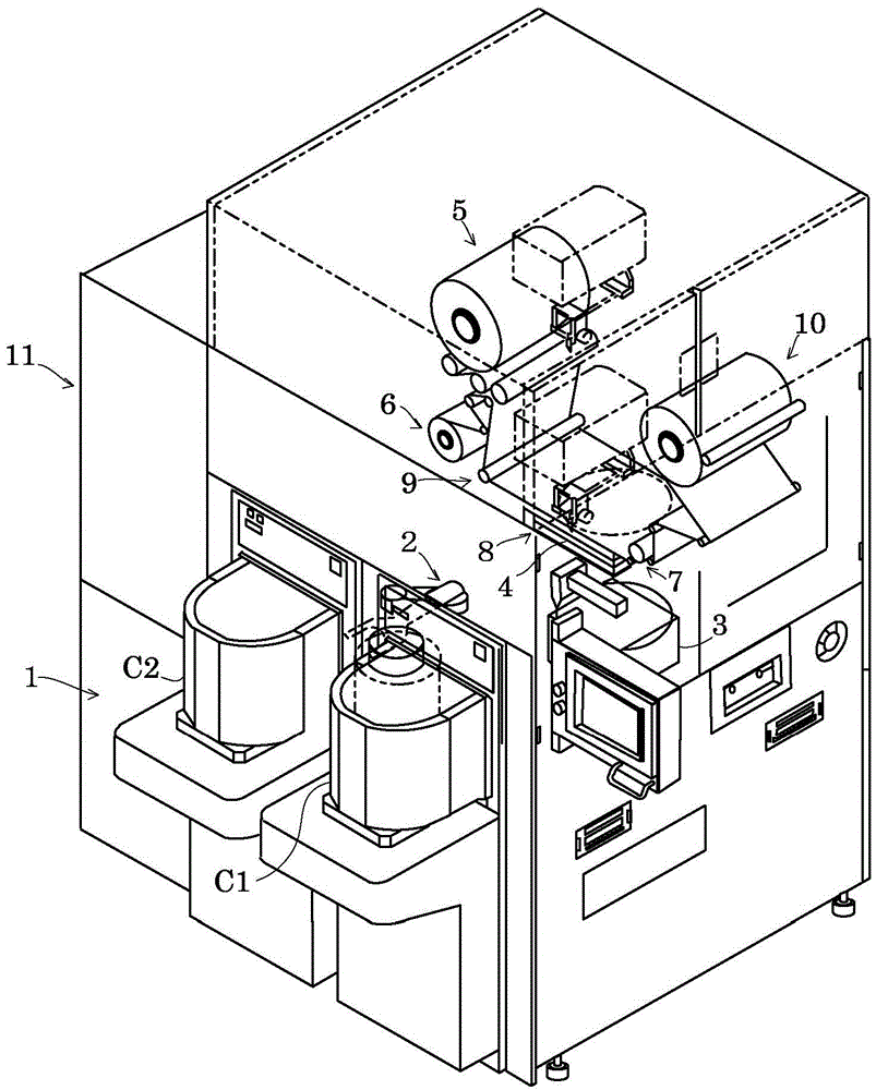
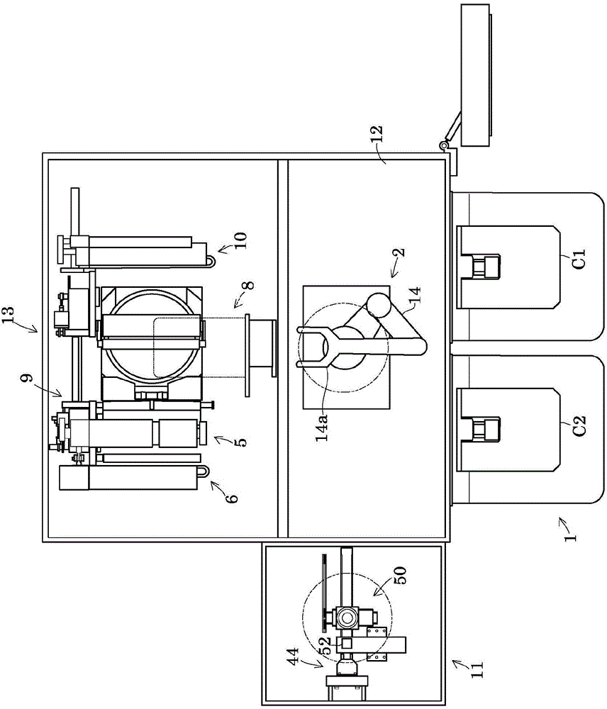
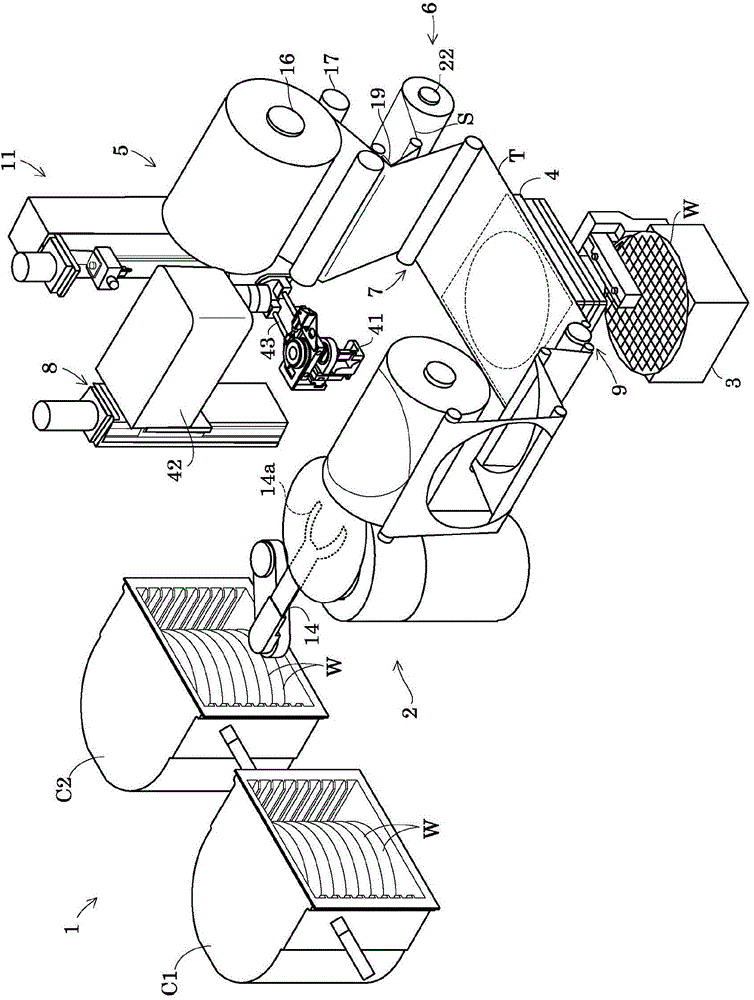
[0046] figure 1 It is a perspective view showing the overall structure of the adhesive tape sticking device, figure 2 It is a top view of the adhesive tape sticking device, image 3 It is a perspective view showing the main part of the adhesive tape sticking device.

[0047] Such as figure 1 with figure 2 As shown, the adhesive tape sticking device includes a wafer supply / recovery unit 1, a wafer transport mechanism 2, an alignment table 3, a holding table 4, a tape supply unit 5, a separator recovery unit 6, a sticking unit 7, and a first cutting The mechanism 8, the peeling unit 9, the tape recovery part 10, the second cutting mechanism 11, and the like. Her...


PUM


Abstract

A strip adhesive tape except for a portion on a notch of a wafer W is cut by contacting a cutter of a first cutting mechanism along an outer periphery of the wafer. The adhesive tape cut out into a wafer shape is reeled and collected while being separated. Thereafter, the wafer with the adhesive tape is transported to a second cutting mechanism. The second cutting mechanism cuts out the portion of the adhesive tape on the notch with a cutter having the same shape as that of the notch.

Description

technical field [0001] The present invention relates to an adhesive tape cutting method for cutting an adhesive tape for protecting the surface of a workpiece such as a semiconductor wafer or an electronic substrate, or an adhesive tape (encapsulating sheet) for encapsulating a circuit surface of a semiconductor wafer or an electronic substrate, etc. and adhesive tape cutting device. Background technique [0002] A method of cutting a protective sheet pasted on a circuit surface of a semiconductor wafer along the outer diameter of the semiconductor wafer is proposed and implemented. In this cutting method, a cutter is provided at the tip of a multi-axis robot arm in which a plurality of arms are rotatably coupled to a longitudinal axis or a swing axis. That is, while changing the angle of the cutter, the cutter is used to cut the protection sheet along the arc portion and the notch portion of the semiconductor wafer (see Japanese Patent Application Laid-Open No. 2007-194321...

Claims


Application Information

Patent Timeline
IPC IPC(8): H01L21/00B26F1/38B26D7/18
CPCB26D3/14B26F1/3846H01L21/67092H01L21/67132Y10T83/2074Y10T83/0467B65H43/00B65H35/06
Inventor 金岛安治石井直树山本雅之
Owner NITTO DENKO CORP
Why Eureka
Try Eureka