Work surface guide for power tools

Inactive Publication Date: 2006-01-31
SANDS WEDEWARD SUSAN A
View PDF17 Cites 7 Cited by
  • Summary
  • Abstract
  • Description
  • Claims
  • Application Information

AI Technical Summary

Benefits of technology

[0006]The board fence 124 includes an inner end 140 facing toward the cutting area 110 and an opposing outer end 142 facing away from the cutting area 110, each of which is adapted to enhance the accurate cutting of boards of different lengths. The inner end 140 of the board fence 124 is adapted to slidably receive a sacrificial elongated cut guide fence member 144 therein, whereby the cut guide fence member 144 may be adjustably extended into the cutting area 110 from the inner end 140 of the board fence 124 (as can be seen from a comparison of FIGS. 3 and 4, wherein FIG. 3 shows the cut guide fence member 144 in a retracted state and FIG. 4 shows it in an extended state). As an example, the inner end 140 of the board fence 124 may be formed of metal tubing sized to complementarily receive a cut guide fence member 144 formed

Problems solved by technology

While the hand-held power tools are popular for their portability and versatility (and additionally their low cost), the more cumbersome and expensive fixed-bed tools are often preferred for a more “professional” job, generally owin

Method used


Image

  • Work surface guide for power tools
  • Work surface guide for power tools
  • Work surface guide for power tools

Examples


Example

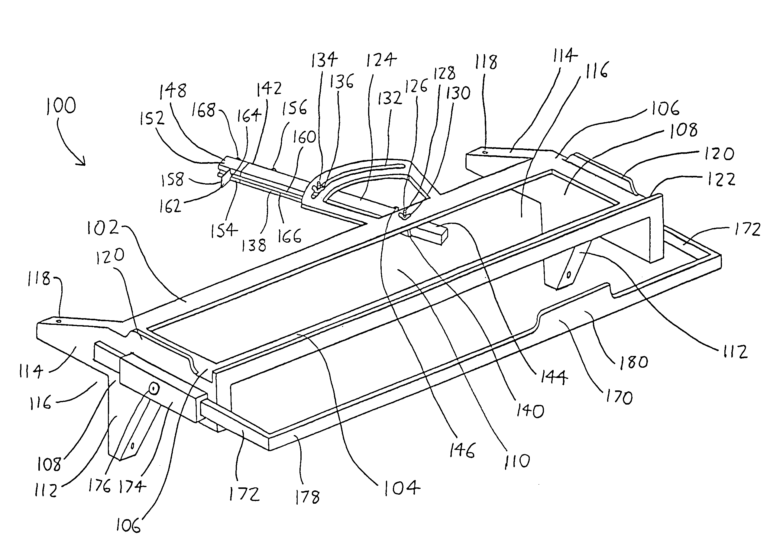
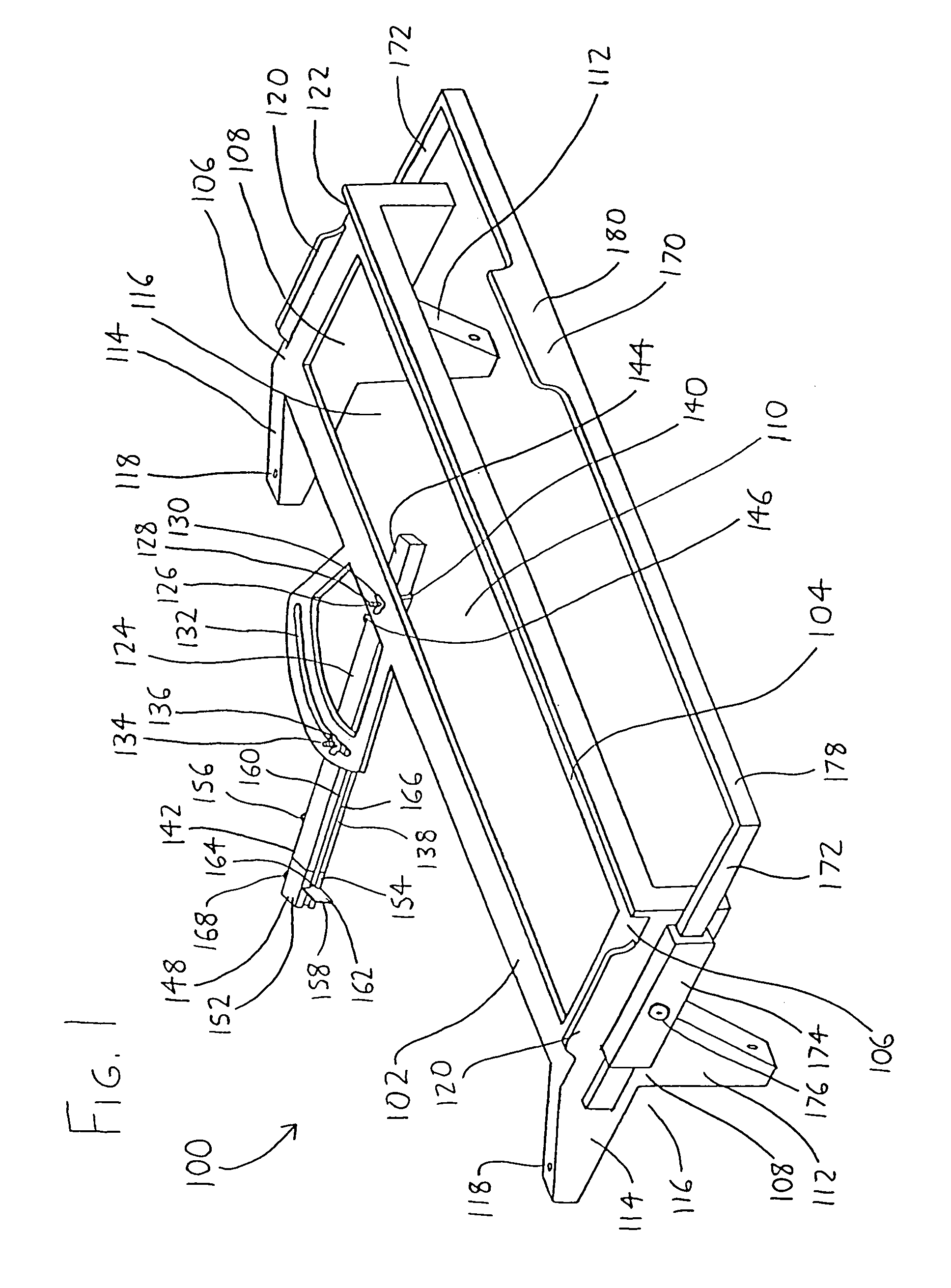
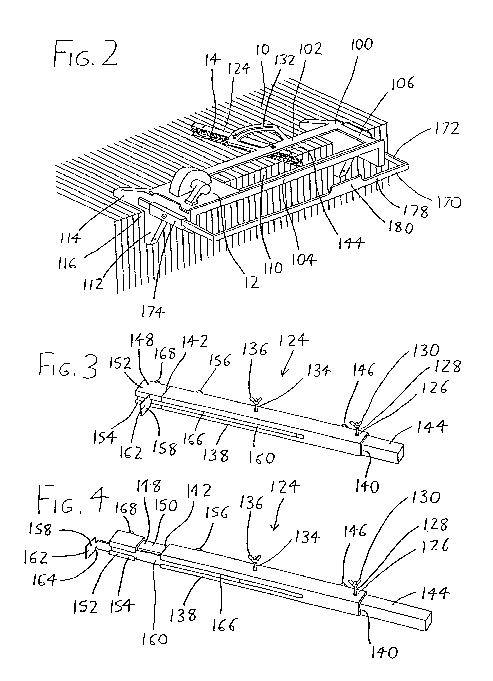
[0014]The reader is directed to FIGS. 1 and 2 of the accompanying drawings, wherein a power tool work surface guide exemplifying the invention is generally designated by the reference numeral 100. The work surface guide 100 includes an elongated inner guide rail 102 and an elongated outer guide rail 104, with the guide rails 102 and 104 being oriented parallel to each other and extending between opposing frame members 106. The frame members 106 are designed to support the guide rails 102 and 104 adjacent to and above a mounting surface such as a workbench or table (generally depicted in FIG. 2 by the reference numeral 10), with the frame members 106 extending downwardly and laterally from the guide rails 102 and 104 to terminate in frame member attachment ends 108. As illustrated in FIG. 2, this allows a power tool such as a circular saw (depicted in FIG. 2 at 12) to rest on the guide rails 102 and 104 with its cutting head (not shown) extending to a cutting area 110 located below a...


PUM

PropertyMeasurementUnit
Lengthaaaaaaaaaa
Areaaaaaaaaaaa

Abstract

A work surface guide for portable hand-operated power tools allows their adaptation to a fixed-bed form (for example, a circular saw may be used as a radial arm saw or sliding miter saw). A pair of parallel rails are spaced laterally outwardly and above a table or other work surface so that the power tool may slide along these rails to cut matter located in a cutting area situated below and beneath the rails (and protruding from the edge of the work surface beneath the rails). A board fence is pivotally attached to one of the rails to extend onto the work surface, thereby allowing the board fence to be adjusted to some desired angle, a board to be situated against the board fence to protrude beneath the rails and into the cutting area, and the power tool to be run along the rails to cut the board.

Description

FIELD OF THE INVENTION[0001]This document concerns an invention relating generally to devices for mounting and guiding power tools with respect to workpieces, and more specifically to an adapter which receives common hand-held power tools and allows them to be operated in a manner similar to larger “fixed bed” power tools (e.g., it allows a common hand-held circular saw to be adapted for use as a radial arm saw or sliding miter saw).BACKGROUND OF THE INVENTION[0002]In fields such as construction and woodworking, users often make use of portable hand-held power tools (such as circular saws, jigsaws, routers, etc.), and / or larger “fixed-bed” power tools (such as table saws, radial arm saws, bandsaws, and table routers). While the hand-held power tools are popular for their portability and versatility (and additionally their low cost), the more cumbersome and expensive fixed-bed tools are often preferred for a more “professional” job, generally owing to their ability to very precisely ...

Claims


Application Information

Patent Timeline
IPC IPC(8): B27C5/04B26D5/00B27B11/02
CPCB27G5/023B23Q9/0092Y10T83/667Y10T83/7627Y10T83/8763
Inventor WEDEWARD, WILLIAM
Owner SANDS WEDEWARD SUSAN A
Why Eureka
Try Eureka