Cut-off device

A technology of cutting device and mounting surface, applied in glass cutting device, fine working device, stone processing equipment, etc., can solve problems such as troublesome work, large deviation, deviation of the surface parallelism of the pressing blade substrate, etc.

Inactive Publication Date: 2017-03-01
MITSUBOSHI DIAMOND IND CO LTD
View PDF9 Cites 4 Cited by
  • Summary
  • Abstract
  • Description
  • Claims
  • Application Information

AI Technical Summary

Problems solved by technology

[0012] However, since the cutting strip of the prior art is formed by a long piece of material, sometimes the tip of the pressing blade may be damaged due to slight errors in the cutting strip main body, including its mounting part, worktable, and its driving mechanism. The parallelism between the ridge line and the substrate surface is slightly deviated
Especially when cutting a large substrate, since the size of the cutting strip becomes longer, the deviation in parallelism becomes larger.
[0013] If the parallelism deviates, it will not be possible to press evenly with an appropriate pressing force over the entire length of the scored line, and it will not be possible to cut perfectly
Therefore, in the prior art such as Image 6 As shown, a thin backing plate (shim) 28 is inserted into the lower side of the lower part of the substrate W to adjust the parallelism, but this operation is very troublesome and time-consuming.

Method used


Image

  • Cut-off device
  • Cut-off device
  • Cut-off device

Examples


Embodiment Construction

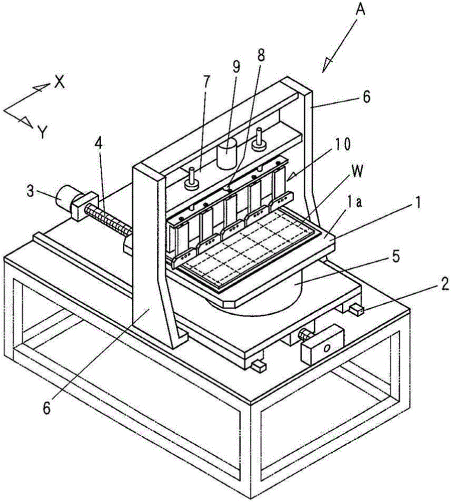
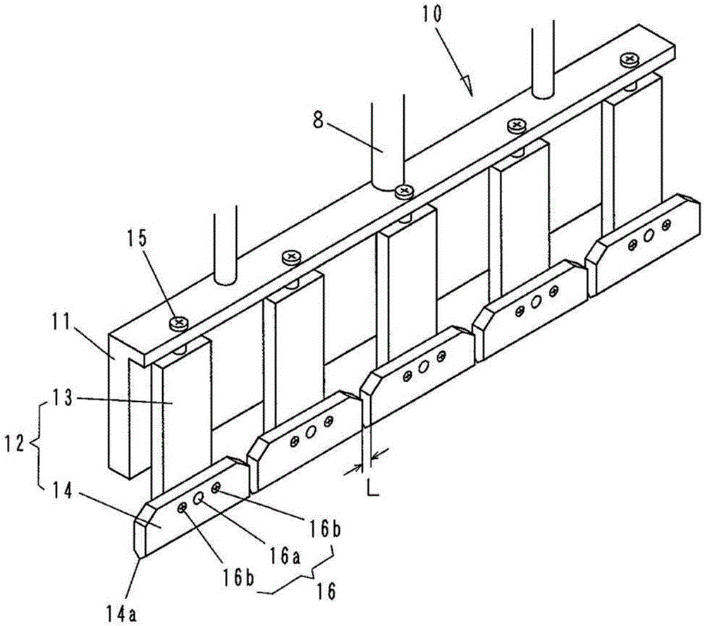
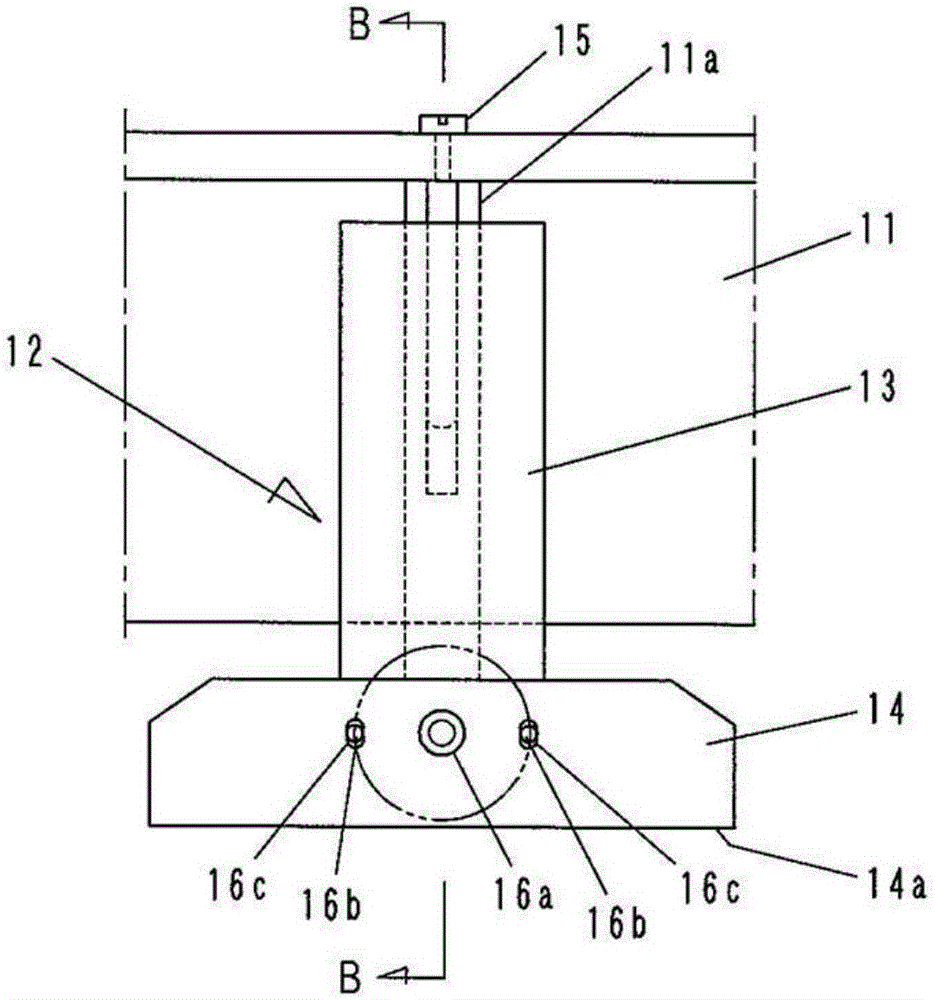
[0028] Hereinafter, details of the cutting device of the present invention will be described based on the accompanying drawings. figure 1 It is a perspective view showing a schematic overall structure of the cutting device of the present invention, Figure 2-4 is showing figure 1 Diagram of the details of the severed strips shown.

[0029] Such as figure 1 As shown, the cutting device A of the present invention is formed to have a table 1 having a mounting surface 1a for mounting a substrate W, and a plurality of suction holes (not shown) are provided on the surface of the table 1. ), the substrate W is adsorbed and held by sucking air through the suction hole.

[0030] In addition, the table 1 can move in the Y direction along the horizontal rail 2 by the screw shaft 4 rotated by the motor 3 . Furthermore, the table 1 can be rotated in a horizontal plane by the rotation drive part 5 which built-in the motor.

[0031] A gate-shaped support body is formed by supporting ...


PUM


Abstract

The invention provides a cut-off device. The cut-off device has a cutting-off bar capable of simply adjusting the parallelism of the top edge ridge of a pressing edge and the surface of a substrate without using a pad or the like. The cut-off device (A) includes a workbench (1), a mounting substrate (W), and a cut-off bar (10) arranged above the workbench (1), wherein the cut-off bar (10) has a plurality of pressing plates (14) arranged in a linear mode and gaps provided between the pressing plates (14).

Description

technical field [0001] The present invention relates to a cutting device for dividing a substrate made of brittle materials such as glass, ceramics, and semiconductor wafers. In particular, the present invention relates to a cutting bar of a cutting device that bends a substrate on which a scribed line (groove) has been formed in a previous process by pressing it from a surface opposite to the scribed line, thereby bending the substrate along the Scribe lines divide the substrate. Background technique [0002] The following methods are known in the prior art, for example, disclosed in Patent Document 1 and Patent Document 2: using a cutter wheel (also referred to as a scoring wheel), a laser beam, etc. Scribe lines in the X direction and Y direction perpendicular to each other are formed on the surface, and the substrate is divided into unit substrates by applying external force along the scribe lines and cutting. [0003] Figure 5 It is a perspective view schematically s...

Claims


Application Information

Patent Timeline
Patent Type & Authority Applications(China)
IPC IPC(8): B28D1/22B28D7/00B28D7/04
CPCB28D1/222B28D1/225B28D7/00B28D7/04B26D7/20B26D7/2628B26F3/002B26F2210/08B28D1/00B28D5/0058C03B33/033C03B33/037H01L21/76H01L21/78
Inventor 冈岛康智曽山正信
Owner MITSUBOSHI DIAMOND IND CO LTD
Why Eureka
Try Eureka