Rotary tool

a technology of rotating tools and rotary tools, which is applied in the direction of turning machine accessories, chucks, manufacturing tools, etc., can solve the problems of more urgent problems such as time-consuming machining operations and large inside diameters of high-precision cutting, and achieve high thermal expansion and high machining performan

Active Publication Date: 2019-10-17
GUEHRING OHG
View PDF7 Cites 5 Cited by
  • Summary
  • Abstract
  • Description
  • Claims
  • Application Information

AI Technical Summary

Benefits of technology

[0005]Therefore, it is the object of the invention to provide a rotary tool especially for the cutting production of large-diameter boreholes which excels, apart from proper handling, by the fact that dimensional stabilities of the borehole not reached so far can be obtained even when high machining performances are required or the thermal input into the tool during machining would result in high thermal expansion thereof.
[0006]The object is achieved with a generic rotary tool according to the invention by the fact that the support structure is designed in light-weight construction and the area of the support structure indirectly or directly supporting the cutting edge is restricted by a corset structure as regards thermal expansion. The supporting area is a portion of the support structure in the environment of the cutting edge which supports the latter indirectly or directly and absorbs the forces occurring at the cutting edge during machining when viewed in the force flux as an upstream area of the support structure. The supporting area and the cutting edge in a way are the main elements of the functional portion of the rotary tool. The support structure meets the requirements of a light-weight construction to minimize the weight and the inertia during rotary machining and of a preferably low-cost manufacture. During heating due to machining, the support structure and especially the supporting area of the support structure expands. According to the invention, the area supporting the cutting edge, viz. the area which is finally decisive for the dimensional stability, is limited as to its expansion due to the corset structure, however. The corset structure has an especially low thermal expansion coefficient so that temperature change results in just very low thermal expansion and, resp., change in geometry which are within a predetermined tolerance of dimensional stability. The corset structure helps to restrict especially the degree of freedom in the radial direction and, in this way, a thermally caused displacement of the cutting edges in the radial direction can successfully be kept within the μm range or can be exactly restricted to few μm, even if the temperature of the cutting edges is very high. Thus, high-precision cutting of components having a large inside diameter is possible.

Problems solved by technology

Especially by the fact that more and more electromotive drives or conventional gearings having a higher number of speeds are required, there is a more urgent problem of high-precision cutting large inside diameters such as e.g. the inside diameter of a stator housing of an electric motor.
If, however, the material removal is to be increased to render manufacture more profitable, further problems will arise:
Since the machining operation is rather time-consuming due to the fact that the surface to be machined is quite large, the support structure is heated and expands corresponding to its thermal expansion coefficient.

Method used


Image

  • Rotary tool
  • Rotary tool
  • Rotary tool

Examples


first embodiment

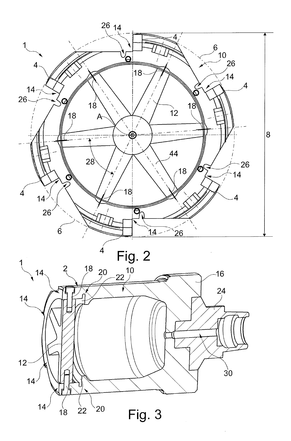
[0054]FIG. 2 shows a front view of the rotary tool 1 according to the invention of the first embodiment from FIG. 1. In the front view the rotationally symmetric design of the rotary tool 1 is visible. More exactly speaking, the rotary tool 1 is divided into six circular portions / sections 28 of equal design which are arranged to be rotated at an angle of 60° relative to each other about the axis of rotation A and thus altogether define the entire cross-section of the rotary tool 1 over 360°.

[0055]In the rotary tool 1 the star-shaped corset structure 12 having six points 44 each pointing radially outwardly into the area 14 supporting the cutting edge 4 are arranged radially inside. In total, the rotary tool 1 comprises, in conformity with the number of points 44 and, resp., the number of circle segments 28, six cutting edges 4. Alternatively, the corset structure 12 may as well be in the form of a circular disk. The support structure 10 includes, when viewed in the circumferential di...

third embodiment

[0064]FIG. 8 illustrates a further, third preferred embodiment of a rotary tool 201 according to the invention. In this Figure, too, for a simplified description, those components of the parts of the afore-described other embodiments are correspondingly provided with similar reference numerals which are preceded by “2”. The rotary tool 201 again includes, in conformity with the foregoing embodiments, at its outer periphery 2 cutting edges 204 at cutting members 226 in the form of cutting inserts which are held in axially and radially adjustable cartridges 205. The cutting edges 4 are supported by two radially outer and diametrically opposed supporting areas 214 of a support structure 210. The support structure 210 in this third embodiment is not in the form of a circular cup but rather in the form of a cup having cut-off sides 216 which are diametrically opposed with respect to the axis of rotation. The cut-off sides 216 serve for improving the handling in logistics and storage of t...


PUM

PropertyMeasurementUnit
temperatureaaaaaaaaaa
densityaaaaaaaaaa
diameteraaaaaaaaaa

Abstract

The invention relates to a rotary tool (1; 101; 201; 301; 401) for cutting large inside diameters at the outer circumference (2) of which at least one cutting edge (4; 104; 204) is arranged, comprising a support structure (10; 110; 210; 310; 410) which includes a supporting area (14; 114; 214) which indirectly or directly supports the cutting edge (4; 104; 204), and comprising a chucking portion (24; 124; 224; 324; 424) for coupling to a tool holder, wherein the support structure (10; 110; 210; 310; 410) is designed in light-weight construction and the area (14; 114; 214) of the support structure (10; 110; 210; 310; 410) indirectly or directly supporting the cutting edge (4; 104; 204) is limited regarding thermal expansion by a corset structure (12; 112; 212; 312; 412).

Description

TECHNICAL FIELD[0001]The present invention relates to a rotary tool / rotating tool for cutting large inside / inner diameters, at the outer circumference of which at least one cutting edge is arranged, the rotary tool comprising a support structure which has a supporting area that indirectly or directly supports the cutting edge, and comprising a chucking portion for coupling to a tool holder. The chucking portion may take any shape, preferably such shape that it can be coupled to the corresponding spindle of a machine tool via common tool holders such as a hollow-shank taper holder (HSK-taper).STATE OF THE ART[0002]Especially by the fact that more and more electromotive drives or conventional gearings having a higher number of speeds are required, there is a more urgent problem of high-precision cutting large inside diameters such as e.g. the inside diameter of a stator housing of an electric motor.[0003]Concerning the efficiency of an electric motor, it is of salient importance to ex...

Claims


Application Information

Patent Timeline
Patent Type & Authority Applications(United States)
IPC IPC(8): B23B31/19B23D77/10B23C5/10
CPCB23B2231/0264B23C5/10B23B31/19B23D2277/02B23B2251/50B23D77/10B23C5/006B23C5/04B23C2222/64B23C2222/88B23C2226/27B23C2250/12B23D77/00
Inventor HAENLE, PETER
Owner GUEHRING OHG
Why Eureka
Try Eureka