Device for adjusting variable guide vanes

a technology of guide vanes and devices, which is applied in the direction of machines/engines, mechanical equipment, liquid fuel engines, etc., can solve the problems of manufacturing costs and weld fatigue, and achieve the effect of reducing these drawbacks

Active Publication Date: 2015-11-17
SIEMENS ENERGY GLOBAL GMBH & CO KG
View PDF7 Cites 8 Cited by
  • Summary
  • Abstract
  • Description
  • Claims
  • Application Information

AI Technical Summary

Benefits of technology

[0015]Structural stability is provided by a stiff casing, so that an additional stabilising beam as can be seen in FIG. 3 (see reference sign 90) can be omitted (see FIG. 4). By omitting the beam a further problem can be excluded which takes place due to thermal expansion of the casing and having no thermal expansion of the beam. Thus mechanical stresses and fatigue used to appear due to the beam, especially in the brackets and its fixation or in welds. This is avoided according to the invention because of the adjustable positioning of the ends of the shaft, so that thermal expansion of the casing will lead to a greater distance of the brackets to each other without resulting in mechanical stress in the shaft or the brackets, because the joints allow adjustable positioning of the shaft, e.g. by sliding to a different position at the shaft.
[0020]According to the invention the first joint and the second joint is a ball-joint and a sliding pin-joint. The pin-joint may allow for adaption a higher thermal expansion of the casing compared to no or lesser thermal expansion of the shaft. The pin-joint allows that the distance of the first joint and the second joint can vary based on the expansion of the casing. The ball-joint may allow the rotation of the shaft.
[0021]The adaption to a larger distance between the first and the second joint, i.e. the adjustable positioning of the ends of the shaft, may additionally be supported by not having a restraining device, wherein the restraining device limits movements of the shaft in an axial direction of the shaft, e.g. a limiting latch or a similar construction at the ends of the shaft that would limit the joints in their divergent movement, so that thermal expansion of the casing will be approximately matched by a similar divergent movement of the joints. Possibly this may be possible if the first end and / or the second end of the shaft will have an unvaried diameter or the diameters even reduce in direction of the head ends of the shaft. A restraining device is particularly a part of the shaft or a piece attached to the shaft that may limit movements of the shaft in axial direction of the shaft.
[0024]Advantageously the first bracket and / or the second bracket may be cast. This may provide a strong stiffness if the cast body has a sufficient thickness and allows cheap manufacturing. Welds may be superfluous in the cast brackets which again removes a potential cause of fatigue failure and removes the costs of having to ensure weld quality.

Problems solved by technology

This provides a good stability but may have disadvantages in regards of manufacturing costs and of fatigue of welds.

Method used


Image

  • Device for adjusting variable guide vanes
  • Device for adjusting variable guide vanes
  • Device for adjusting variable guide vanes

Examples


Embodiment Construction

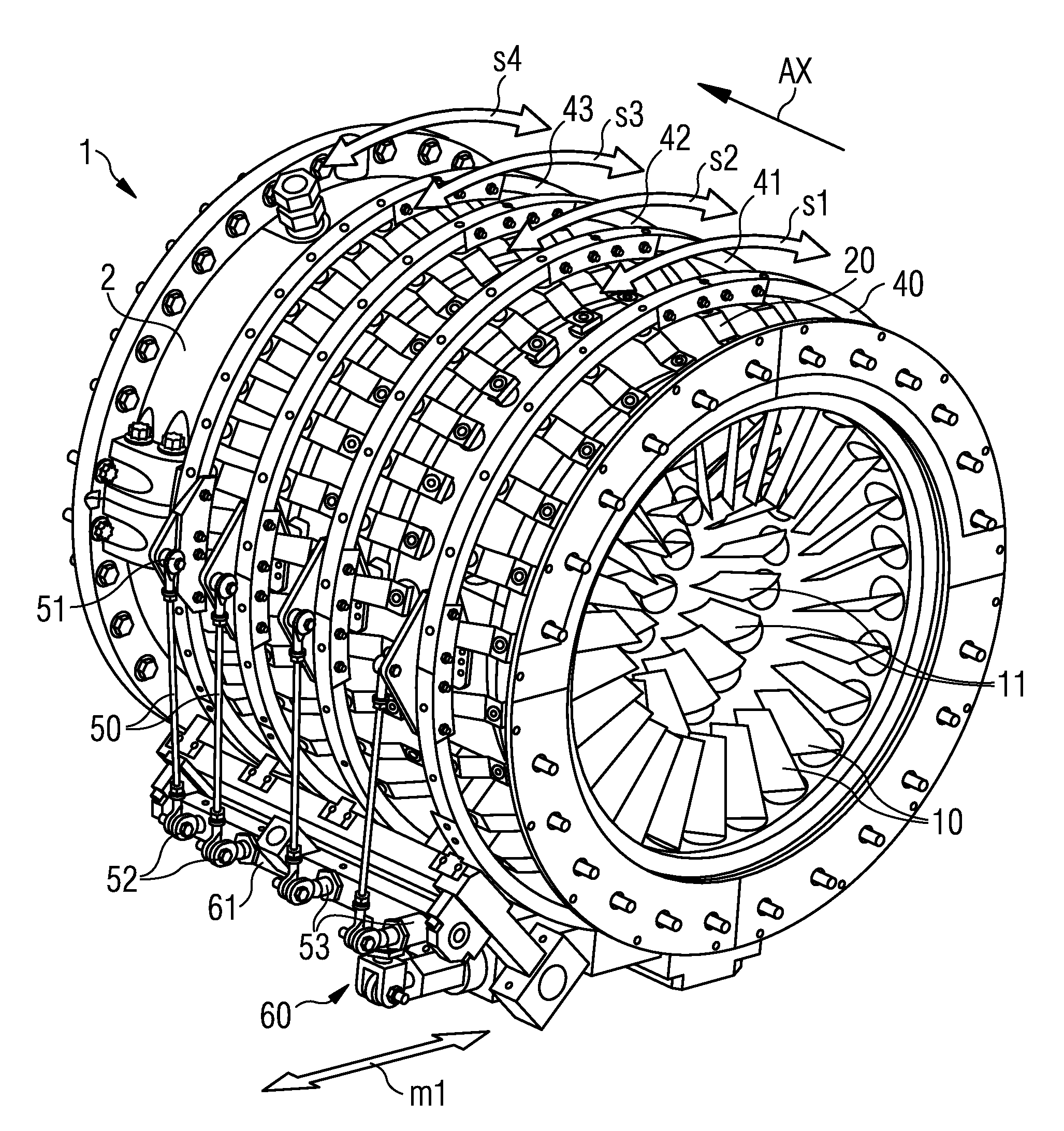
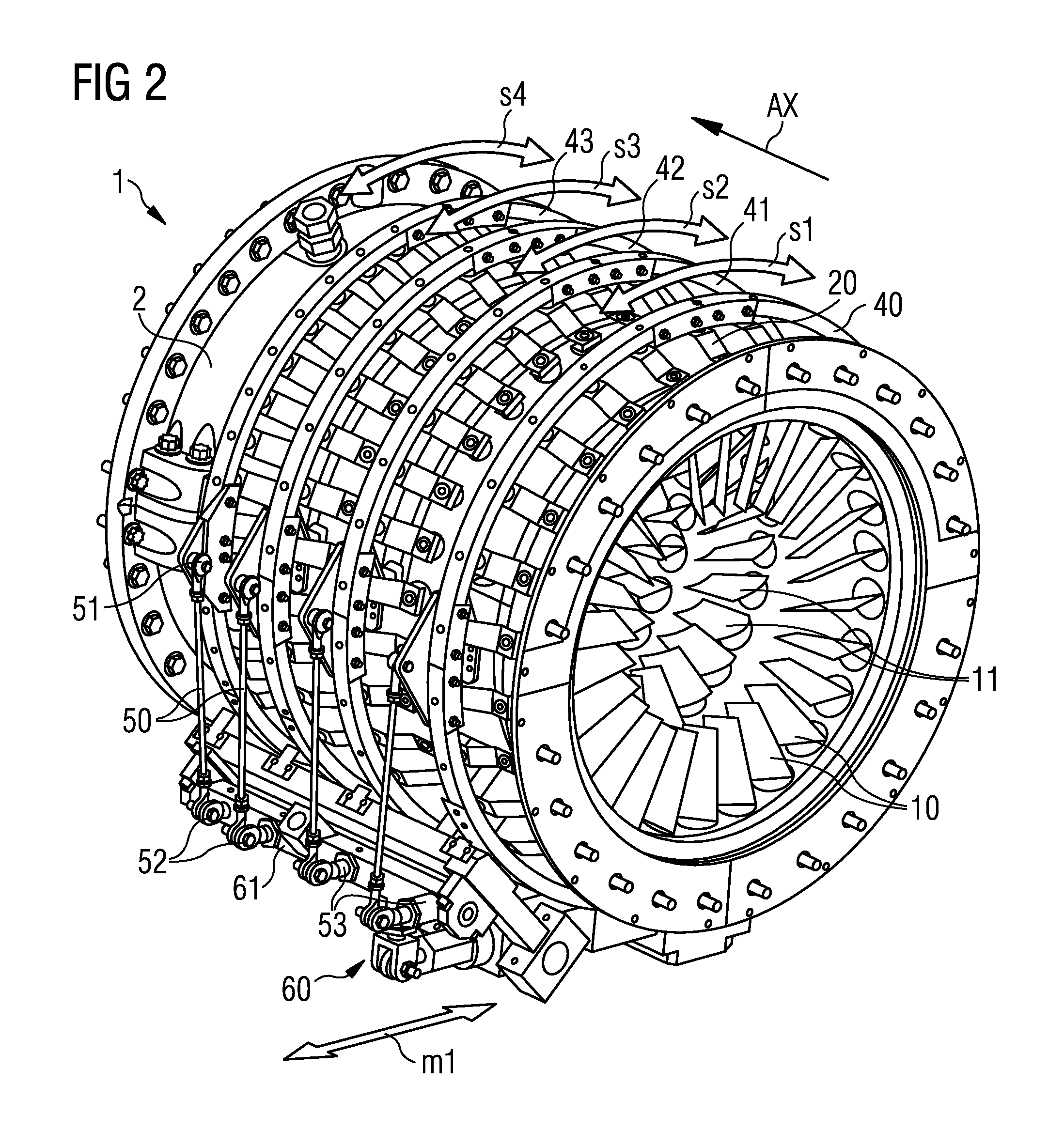
[0039]The invention may particularly be applied to a gas turbine engine that can generally include a compressor section 1 (see FIG. 2), a combustor section (not shown) and a turbine section (not shown). A centrally disposed rotor (not shown) can extend through these three sections. The compressor section 1 can include alternating rows of vanes 10, 11, . . . and rotating blades (not shown).

[0040]The invention is directed to a compressor with “Variable Guide Vanes” (VGV). This is a construction with variable pitch of the stator vanes 10, 11, . . . .

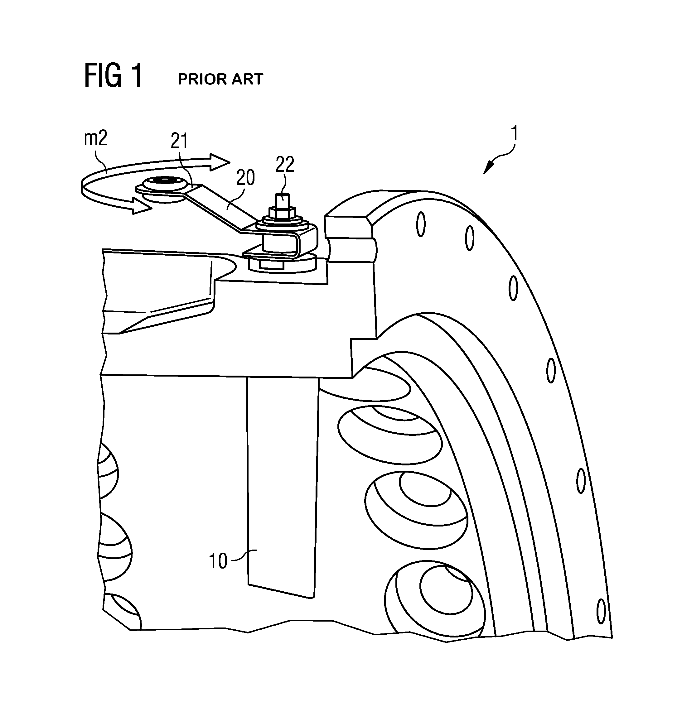
[0041]Based on FIGS. 1, 2, and 3 the general concept of “Variable Guide Vanes” is explained. These concepts also apply to the invention. Differences to the invention will be explained later, in regards of FIG. 4.

[0042]The pitch or the angular offset for an individual stage of variable guide vanes inside of the compressor wall is controlled via a linkage mechanism which is applied from the outside of the wall. Each individual first stage gui...


PUM


Abstract

A device for adjusting variable guide vanes of an axial-flow machine includes a control rod that adjusts an angular position of the variable guide vanes and is pivotably connected to a shaft. Each of a first and a second bracket has a first end connectable to a casing of the machine. A first joint is fixed to a second end of the first bracket and provides adjustable positioning of a first end of the shaft. A second joint is fixed to a second end of the second bracket and provides adjustable positioning of a second end of the shaft. The two joints are spatially positioned to each other solely via a first fixed connection between the first end of the first bracket to the casing and via a second fixed connection between the first end of the second bracket to the casing.

Description

CROSS REFERENCE TO RELATED APPLICATIONS[0001]This application is the US National Stage of International Application No. PCT / EP2010 / 067656, filed Nov. 17, 2010 and claims the benefit thereof. The International Application claims the benefits of European application No. 10000879.6 EP filed Jan. 28, 2010. All of the applications are incorporated by reference herein in their entirety.FIELD OF THE INVENTION[0002]The invention relates to a device for adjusting variable guide vanes, a compressor and a gas turbine engine including such a device.BACKGROUND OF THE INVENTION[0003]A gas turbine engine comprises a turbine and a compressor driven by the turbine, the compressor may be of an axial flow type. Commonly, the gas turbine engine is subjected to varying operating conditions resulting in different aerodynamic flow conditions within the compressor. In order to adapt the compressor performance to different operating demands, it is known to provide the compressor with variable guide vanes (V...

Claims


Application Information

Patent Timeline
Patent Type & Authority Patents(United States)
IPC IPC(8): F04D29/56F01D17/16
CPCF04D29/563F01D17/162F05D2260/79
Inventor KEEGAN, COLMTIBENHAM, MICHAEL
Owner SIEMENS ENERGY GLOBAL GMBH & CO KG
Why Eureka
Try Eureka