Device and method for cutting an assembly

a technology of assembly and device, applied in the field of substrate preparation, can solve the problems of not providing specific advantages, not teaching how to precisely control the pressure in two different zones, and not enabling one to control the pressure in one single high-pressure zon

Inactive Publication Date: 2007-06-19
SOITEC SA
View PDF8 Cites 5 Cited by
  • Summary
  • Abstract
  • Description
  • Claims
  • Application Information

AI Technical Summary

Benefits of technology

[0011]A method is presented for cutting an assembly that includes two layers of material having a first surface and a second surface. The method includes providing a weakened interface between the two layers that defines an interface ring about the periphery of the assembly, providing a high-pressure zone at the interface ring, and providing at least one controllable low-pressure zone in the vicinity of at least one of the first surface and the second surface. The technique also includes supplying the high-pressure zone with a controllable high-pressure force, and attacking the interface ring with at least one mechanical force in combination with the high-pressure force to cut the assembly. The method provides high-precision cutting of the two layers.

Problems solved by technology

A limitation of the disclosure of this document is that it only enables cutting of layers that have been previously bonded together, so that the weakened interface is necessarily a bonding interface.
But that method does not provide the specific advantages of the type of method described in International Application No.
In particular, the method does not teach how to precisely control the pressure in the two different zones (corresponding to the high-pressure zone and the low-pressure zone mentioned above).
The device described in U.S. Pat. No. 6,221,740 thus does not enable one to control the pressure in one single zone of high pressure, which is adjacent to at least one part of the interface ring.
And it must be noted that even this control cannot be carried out in a precise manner due to the significant risk of leakage at the interface ring (a certain tightness being provided by an O-ring seal positioned relative to the interface ring), although as stated in U.S. Pat. No. 6,221,740 (see col.
Furthermore, U.S. Pat. No. 6,221,740 does not have the advantageous structure type described in International Application No.

Method used


Image

  • Device and method for cutting an assembly
  • Device and method for cutting an assembly
  • Device and method for cutting an assembly

Examples


Embodiment Construction

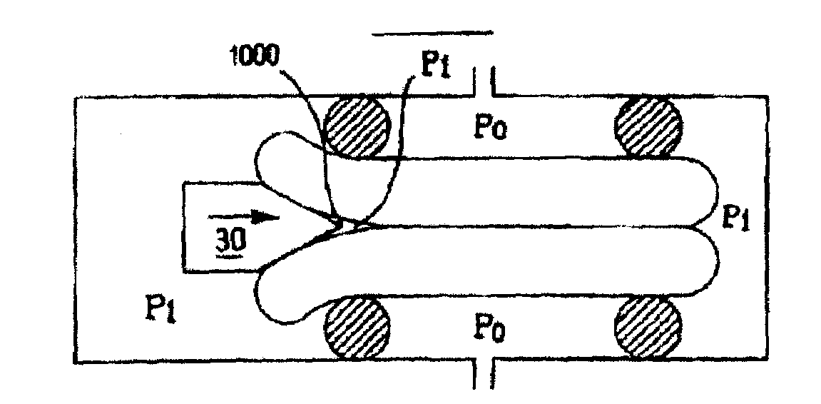
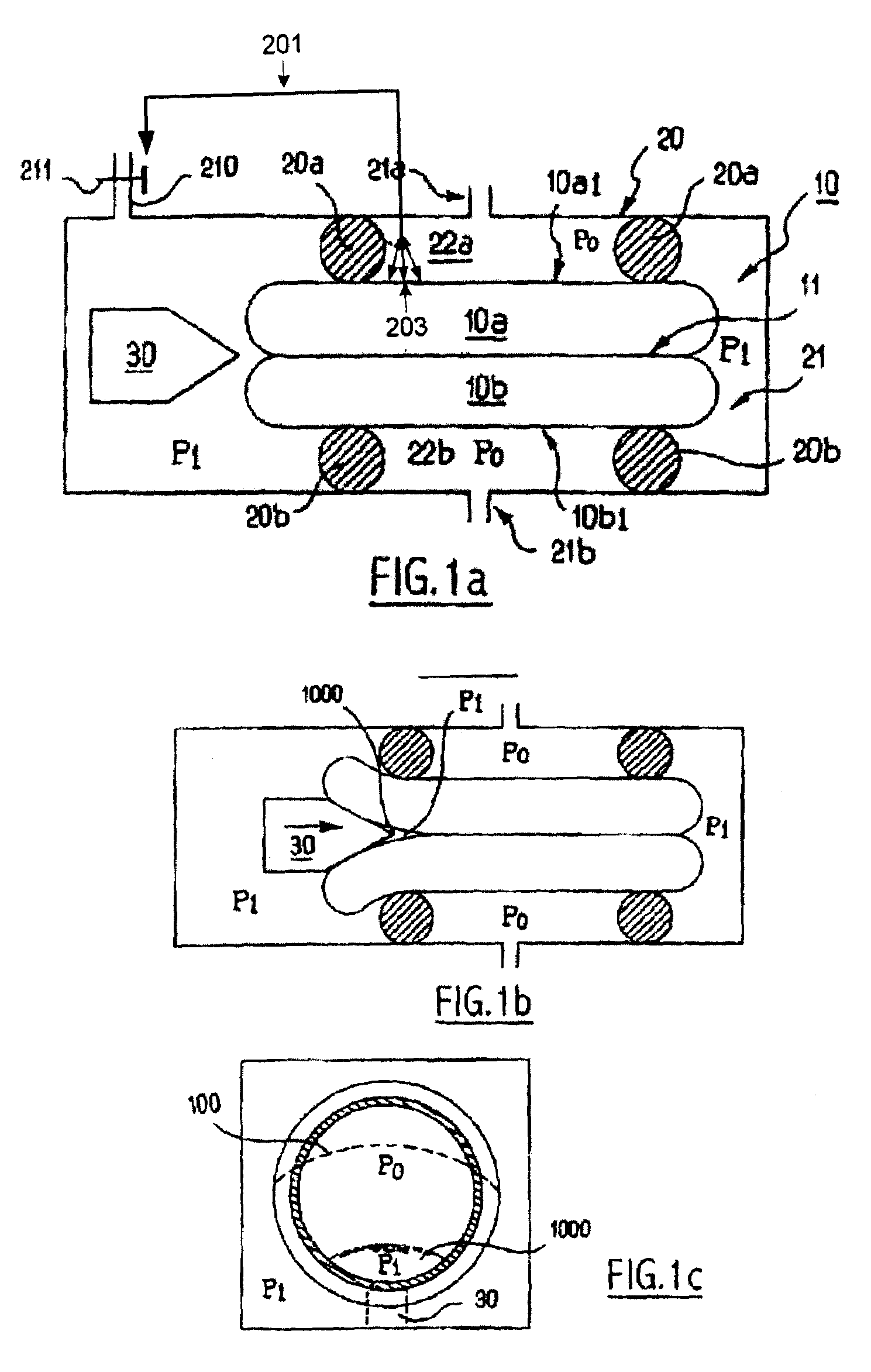
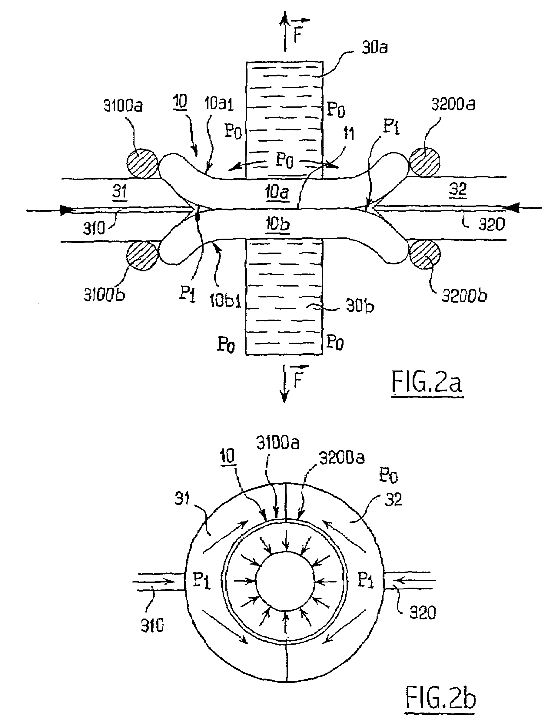
[0024]By way of introduction to the following description of different alternative embodiments of the invention, it should be noted that the examples described below represent cutting an assembly 10 that includes two layers of material separated by a weakened interface. The two layers are arranged on either side of the weakened interface and can be made of the same material or of different materials. The weakened interface can be produced by any known method. In particular, the weakened interface can be produced by implanting elements as hereinbefore mentioned, or even by any other known means (for example, by forming a thin porous layer between the two layers which then corresponds to the weakened interface).

[0025]It is also noted that, although the figures illustrating the assembly show two relatively thick layers, in reality these layers can be extremely thin. In particular, in one preferred application of the invention, the assembly can be a Silicon-On-Insulator (SOI) substrate ...


PUM

PropertyMeasurementUnit
pressureaaaaaaaaaa
traction forceaaaaaaaaaa
shearing forceaaaaaaaaaa

Abstract

A method is presented for cutting an assembly that includes two layers of material having a first surface and a second surface. The method includes providing a weakened interface between the two layers that defines an interface ring about the periphery of the assembly, providing a high-pressure zone at the interface ring, and providing at least one controllable low-pressure zone in the vicinity of at least one of the first surface and the second surface. The technique also includes supplying the high-pressure zone with a controllable high-pressure force, and attacking the interface ring with at least one mechanical force in combination with the high-pressure force to cut the assembly.

Description

CROSS-REFERENCE TO RELATED APPLICATIONS[0001]This application is a continuation of International application no. PCT / FR02 / 04594 filed Dec. 31, 2002, the entire contents of which are expressly incorporated herein by reference thereto.BACKGROUND ART[0002]The present invention relates generally to preparing substrates for electronics, optics or optoelectronics. More specifically, the invention relates to a method for precisely cutting an assembly formed of two layers of material that has two principal surfaces. The method includes providing a weakened interface between the two layers, wherein the interface defines an interface ring at the periphery of the assembly. A first high-pressure zone is provided whose border includes at least one part of the interface ring, and at least one second low-pressure zone is formed whose pressure is controlled relative to one part at least of a principal surface of the assembly. The high-pressure zone is supplied with a fluid, whose pressure is contro...

Claims


Application Information

Patent Timeline
Patent Type & Authority Patents(United States)
IPC IPC(8): H01L21/46B28D5/04B28D5/00H01L21/20H01L21/762
CPCB28D5/0011B28D5/0023B28D5/0052B28D5/0064H01L21/2007H01L21/76254Y10T156/1184Y10T156/1126Y10T156/1928Y10T156/1972Y10T156/1967Y10T83/364
Inventor RAYSSAC, OLIVIERLETERTRE, FABRICE
Owner SOITEC SA
Why Eureka
Try Eureka