
MEMS electric field energy collector based on electret

An electric field energy, collector technology, applied in piezoelectric effect/electrostrictive or magnetostrictive motors, electrical components, generators/motors, etc., can solve problems such as limited use range, large environmental impact, power failure, etc. , to achieve the effect of benefiting system integration and mass production, enhancing sensitivity and output energy, and reducing costs

Active Publication Date: 2014-09-03
TSINGHUA UNIV
View PDF4 Cites 2 Cited by
  • Summary
  • Abstract
  • Description
  • Claims
  • Application Information

AI Technical Summary

Problems solved by technology

Fault detection nodes are usually suspended on overhead high-voltage lines, and there will be great difficulties in using conventional methods to supply power to detection nodes
At present, the following solutions include: 1) battery, which is not affected by the surrounding environment by using battery power supply, but the battery life is limited and needs to be replaced frequently; 2) solar battery, solar battery is a good way, but it is affected by the environment 3) High-voltage current induction power supply, this method relies on the magnetic circuit of the alternating current in the high-voltage line to pass through the coil to induce energy, the principle is similar to a transformer; the disadvantage is that the current intensity in the high-voltage line varies with the user's use The power situation will change greatly, resulting in very unstable energy supply, and even the possibility of power outages

Method used


Image

  • MEMS electric field energy collector based on electret

Examples


Embodiment Construction

[0018] The present invention will be further described below with reference to the embodiments and the accompanying drawings.

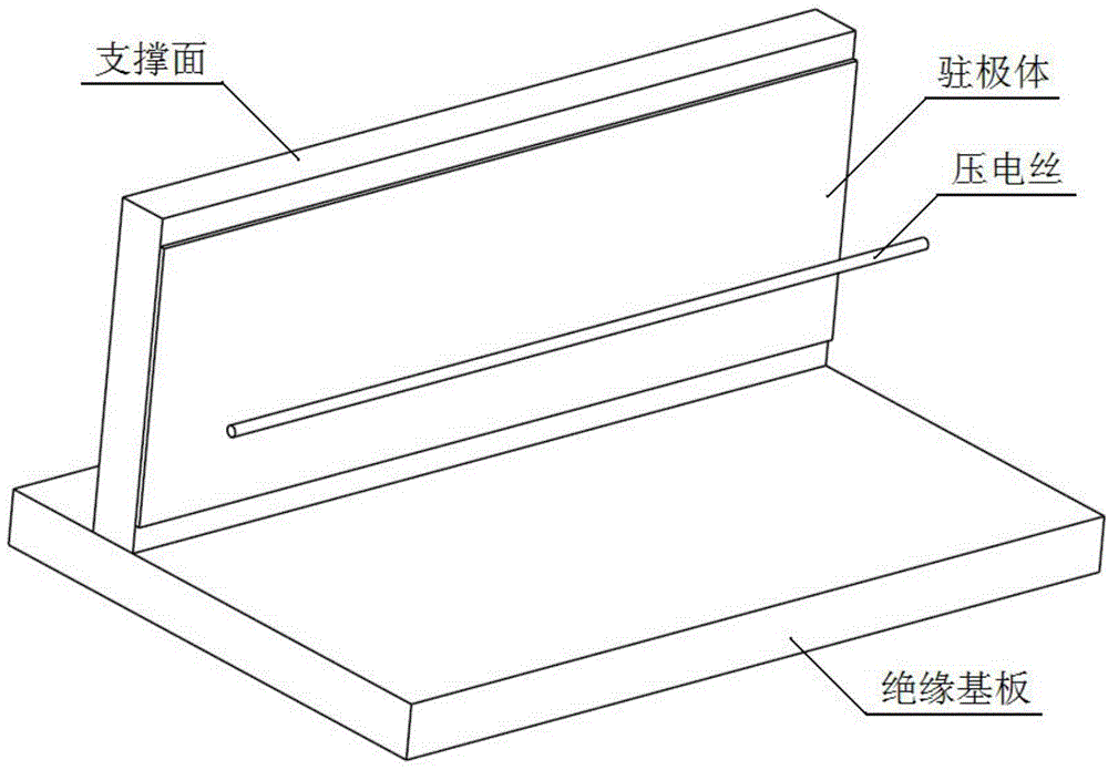
[0019] An electret-based MEMS electric field energy collector proposed by the present invention, such as figure 1 As shown, it is mainly composed of an insulating substrate, a piezoelectric wire, a supporting surface, and an electret.

[0020] The insulating substrate is placed horizontally at the bottom of the sensor, and the piezoelectric wire is placed parallel to the insulating substrate.

[0021] The support surface is made of insulating material, is vertically fixed on the insulating substrate, and keeps a certain distance from the piezoelectric wire.

[0022] The electret is adhered to the support surface, and is adhered with electret tape or liquid electret glue.

[0023] The piezoelectric wire is connected to the external circuit.

[0024] The energy harvester works as follows:

[0025] After the electret on the support surface passes thr...


PUM


Abstract

The invention belongs to the technical field of energy collection, in particular to an MEMS electric field energy collector based on an electret. The MEMS electric field energy collector based on the electret is mainly used for collecting energy of an alternating-current electric field in a space. The MEMS electric field energy collector based on the electret comprises an insulating substrate, a piezoelectric wire, a supporting surface and the electret, wherein the piezoelectric wire is arranged above the insulating substrate in parallel, an electrostatic field composed of the electret adhering to the supporting surface provides appropriate bias for the piezoelectric wire located in the electrostatic field, sensitivity of the piezoelectric wire biased by the electrostatic field to an external electric field is greatly improved, when the piezoelectric wire vibrates due to excitation of the external electric field, a piezoelectric material carries out stress-strain due to stretching or shrinkage so that internal electric charges flow to form electrical signals, and mechanical energy can be converted into electric energy; electric field energy is collected through an external circuit connected with the piezoelectric wire. The MEMS electric field energy collector based on the electret is manufactured through the MEMS micromachining technology, electric field energy in a space is used creatively, and the collector is small in size, convenient to carry and low in cost.

Description

technical field [0001] The invention belongs to the technical field of energy collection and utilization, and in particular relates to an electret-based MEMS electric field energy collector. Background technique [0002] The operation state of high-voltage transmission lines directly determines the safety and efficiency of power grid operation, and the real-time monitoring of its operation state is generally by installing fault detection nodes. The fault detection node is usually suspended on an overhead high-voltage line, and it is very difficult to supply power to the detection node in a conventional way. At present, there are the following solutions: 1) Batteries, which are not affected by the surrounding environment when using batteries for power supply, but the battery life is limited and needs to be replaced frequently; 2) Solar cells, solar cells are a good method, but are affected by the environment 3) High-voltage current induction power supply, this method relies ...

Claims


Application Information

Patent Timeline
Patent Type & Authority Applications(China)
IPC IPC(8): H02N2/18
Inventor 黄景傲伍晓明边潍
Owner TSINGHUA UNIV
Learn More