Pressure forming method and pressure forming device

A pressure and forming surface technology, applied in forming tools, metal processing equipment, manufacturing tools, etc., can solve the problems of reduced forming allowance and poor forming, and achieve the effects of increased material yield, strain relief, and high tensile rigidity

Inactive Publication Date: 2016-05-25
MS KK
View PDF6 Cites 0 Cited by
  • Summary
  • Abstract
  • Description
  • Claims
  • Application Information

AI Technical Summary

Problems solved by technology

As the main reason, there is the following fatal problem: If the plate-shaped workpiece is stretched in advance as in the proposed method, the forming tolerance is reduced before forming, so the portion with a long cross-sectional actual length is not supplied during forming. Deformation due to material

Method used


Image

  • Pressure forming method and pressure forming device
  • Pressure forming method and pressure forming device
  • Pressure forming method and pressure forming device

Examples


Embodiment Construction

[0040] Hereinafter, the pressure forming method and the pressure forming apparatus related to the present invention will be specifically explained with reference to the drawings.

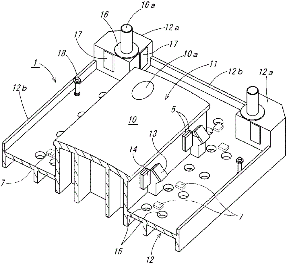
[0041] The pressure forming apparatus of the first embodiment of the present invention is such as figure 1 As shown, a punch-side metal mold 1 as a fixed lower die mounted on a base (not shown) is used as a movable upper die, which is opposed to and fixed on the lower surface side of the indenter (not shown) The die side mold 2 is composed of four independent blanking rings 3..., and a rectangular frame-shaped holder support member 4, which clamps and constrains the peripheral portion of the rectangular plate-shaped workpiece P1 on each side. In addition, each blank holder 3 is composed of a first clamping member 3a held on the punch side via a clamper support member 4, and a second clamping member 3b held on the die side.

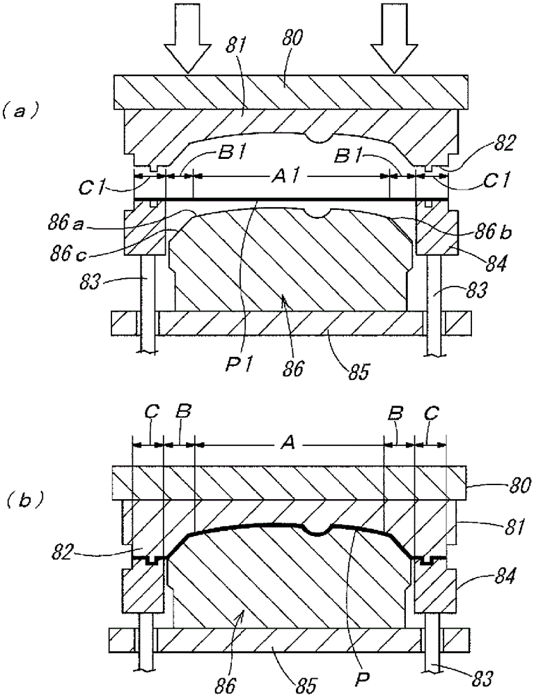
[0042] Punch side metal mold 1 as in figure 2 As shown in FIG. 1, a punch 11 h...


PUM


Abstract

Provided is a means for efficiently imparting high tensile stiffness to a press stamping product by high forming stability, wherein that means can narrow a sacrificial constricted part, can greatly improve material yields, and can effectively resolve strain due to actual cross-sectional length differences in punch shapes in press forming accompanied by restriction of a sheet-shaped workpiece. When pressing between a punch (11) and a die (21) accompanied by expansion from a peripheral side while constraining the peripheral part of the sheet shaped workpiece (P1) by a plurality of blank holders (3) formed from a pair of sandwiching members (3a, 3b), in a process up to pressing after contact of a sheet shaped workpiece (P1) with a forming surface (10) of the punch (11), each blank holder (3) is displaced in the pressing direction and the sheet shaped workpiece (P1) is superimposed on the forming surface (10) of the punch (11), and then displaced in the outside direction and the sheet shaped workpiece (P1) is expanded. After completion of pressing, each blank holder (3) is displaced along the opposite of the pressing direction, and the press stamping product (P1) is disengaged from the punch (11). Furthermore, after both sandwiching members (3a, 3b) are made to detach and the press stamping product (P) removed, both sandwiching members (3a, 3b) are displaced toward the inside direction, and a sheet shaped workpiece (P1) is returned to an initial position prior to being constrained.

Description

Technical field [0001] The present invention relates to a pressure forming method and a pressure forming apparatus for producing a pressure forming product that requires high tensile rigidity, such as automobile body panels. Background technique [0002] In the past, as a method of producing a press-formed article such as a body panel of an automobile from a plate-shaped workpiece composed of a thin metal plate, a drawing press forming method called a tension work method has been widely used. The drawing pressure forming method is, for example, Picture 12 As shown, the peripheral part of the plate-shaped workpiece P1 is clamped and restrained between the peripheral clamping portion 82 of the die 81 fixed on the indenter 80 and the blanking ring 84 elastically supported by the buffer pin 83, and the restrained state The plate-shaped workpiece P1 is drawn by drawing from the peripheral side while being pressed between the die 81 and the punch 86 fixed to the base 85, thereby formin...

Claims


Application Information

Patent Timeline
Patent Type & Authority Patents(China)
IPC IPC(8): B21D24/04B21D24/14B21D25/02B21D37/08
CPCB21D24/04B21D22/22
Inventor 胜间秀人森泉宗次
Owner MS KK
Why Eureka
Try Eureka