
Method and device for manufacturing optical display device
An optical film and detection device technology, applied in chemical instruments and methods, optics, nonlinear optics, etc., can solve the problem of not exerting a peeling effect, etc.
- Summary
- Abstract
- Description
- Claims
- Application Information
AI Technical Summary
Problems solved by technology
Method used
Image

Examples
Embodiment Construction
[0064]
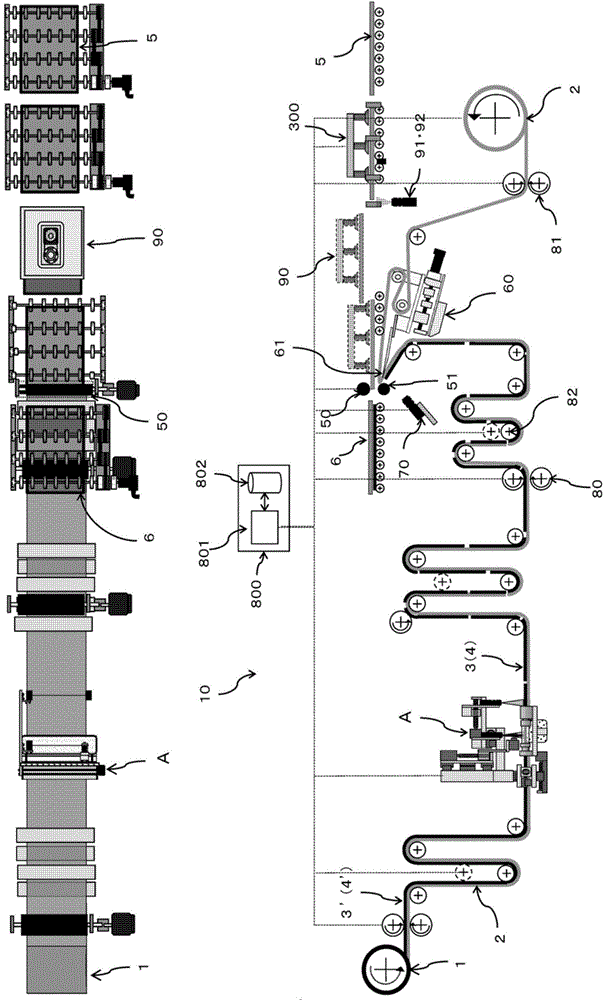
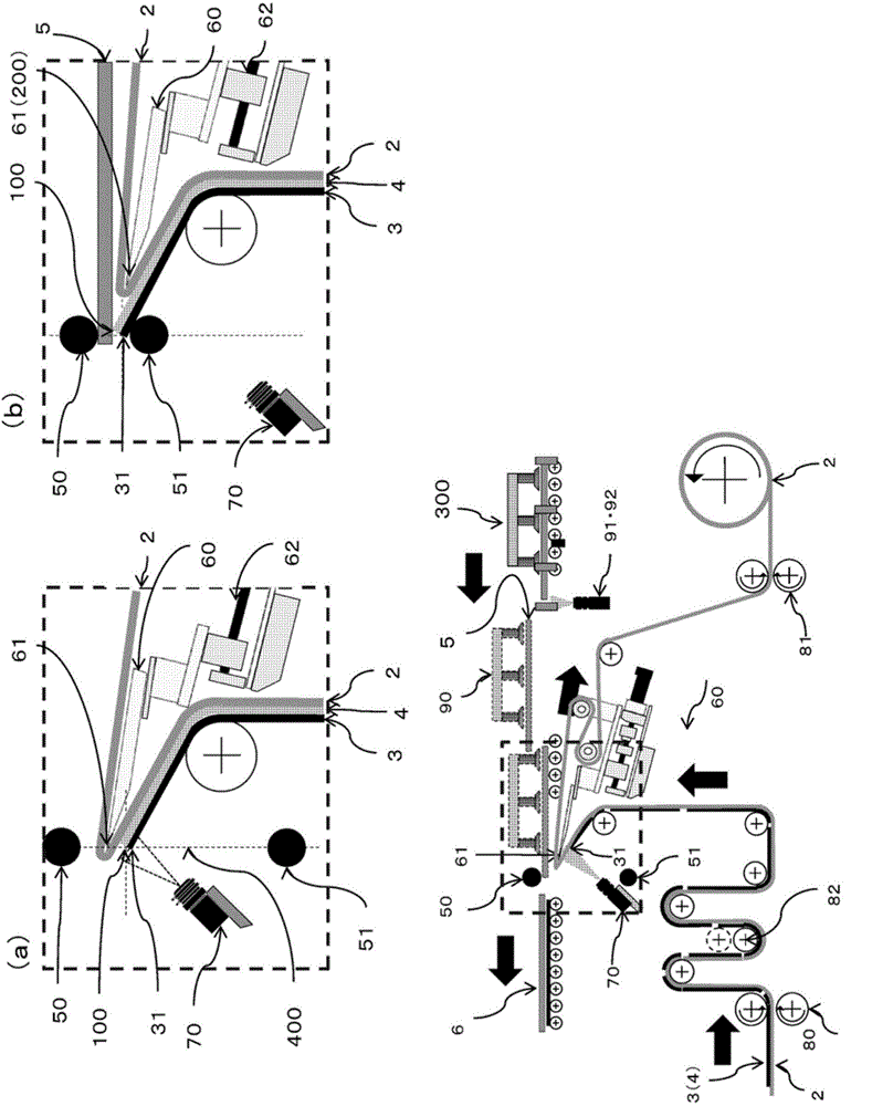
[0065] figure 2 It is a top view and a side view which show the whole apparatus 10 which manufactures the optical display device 6 by bonding the optical film sheet 3 and the panel member 5 at the predetermined attachment position 100. Among them, the laminating rollers 50, 51 configured to open and close in the up and down direction with respect to the conveying direction are arranged at the predetermined sticking position 100, and the movable peeling body 60 is arranged. The space 400 between the closing rolls 50 and 51 is movable between the space 400 and the work start position 200 .
[0066] Depend on image 3 It can be seen that the carrier film 2 supports the front end 31 of the optical film sheet 3 in a state wound on the movable peeling body 60, and the carrier film 2 is in a state where the back side is folded back inwardly at the top 61 constituting the front end portion of the movable peeling body 60. The state of being wound on the movable peeling bod...
PUM
| Property | Measurement | Unit |
|---|---|---|
| mass | aaaaa | aaaaa |
| mass | aaaaa | aaaaa |
| diameter | aaaaa | aaaaa |
Abstract
Description
Claims
Application Information