Lathe machining method for end face deep narrow groove in aerial engine crankcase

A technology of aero-engine and processing method, applied in the field of aero-engine casing processing, can solve the problems of bending deformation, large cutting force, difficult chip removal, etc., and achieves reduction of thermal deformation and bending deformation, high machining accuracy, and reduced offset Effect

Inactive Publication Date: 2014-09-10
CHINA HANGFA SOUTH IND CO LTD
View PDF5 Cites 17 Cited by
  • Summary
  • Abstract
  • Description
  • Claims
  • Application Information

AI Technical Summary

Problems solved by technology

The processing process of the above-mentioned deep and narrow groove 1 on the end face is mainly to use a groove cutter with the same blade width as the expected width of the deep and narrow groove on the end face, and perform one feed to form the deep and narrow groove 1 on the end face. Big, difficult chip removal, easy to hit the knife problem, such as figure 2 As shown, the actual deep and narrow groove 3 on the end face processed by the groove cutter 2 (the solid line area in the figure) is different from the expec

Method used


Image

  • Lathe machining method for end face deep narrow groove in aerial engine crankcase
  • Lathe machining method for end face deep narrow groove in aerial engine crankcase
  • Lathe machining method for end face deep narrow groove in aerial engine crankcase

Examples


Embodiment Construction

[0019] It should be noted that, in the case of no conflict, the embodiments in the present application and the features in the embodiments can be combined with each other. The present invention will be described in detail below with reference to the accompanying drawings and examples.

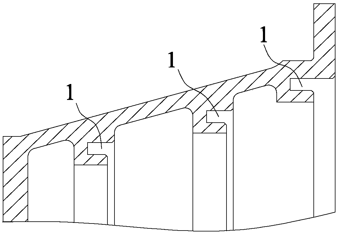
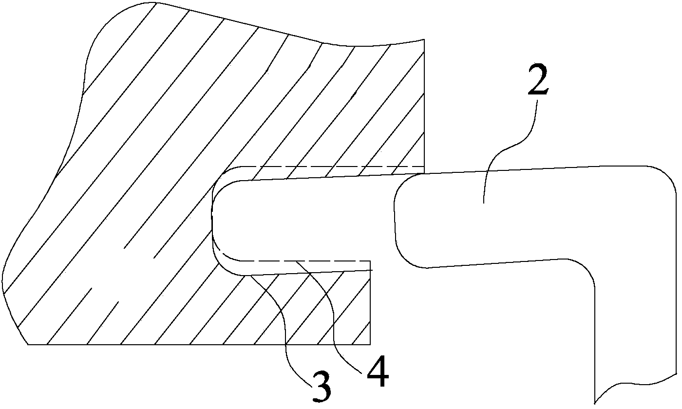
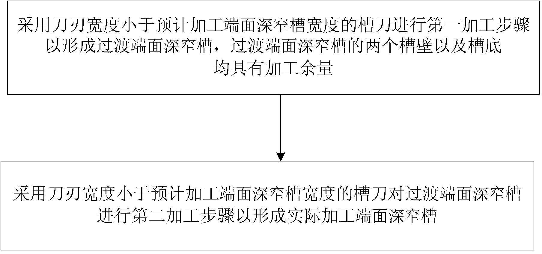
[0020] Such as image 3 As shown, the turning processing method of the deep and narrow groove on the end face of the aero-engine casing of the present embodiment includes a first processing step and a second processing step, and the first processing step is performed by using a groove cutter with a blade width smaller than the width of the expected deep and narrow groove on the end face to be machined. Form the deep and narrow groove on the transition end face, carry out the second processing step on the deep and narrow groove on the transition end face, remove the machining allowance on the deep and narrow groove on the transition end face to form the deep and narrow groove on the actual proce...


PUM


Abstract

The invention provides a lathe machining method for an end face deep narrow groove in an aerial engine crankcase. The method comprises the following machining steps: 1, using a groove cutter to carry out the first machining step to form a transition end face deep narrow groove, wherein the width of a blade of the groove cutter is less than that of the end face deep narrow groove to be machined, and at least two opposite groove walls of the transition end face deep narrow groove have machining allowances; 2, removing the machining allowances of the transition end face deep narrow groove to form the actually machined end face deep narrow groove. According to the lathe machining method, the machined end face deep narrow groove is higher in machining precision.

Description

technical field [0001] The invention relates to the technical field of aero-engine casing processing, in particular to a method for turning deep and narrow grooves on an end face of an aero-engine casing. Background technique [0002] At present, titanium alloy casings and superalloy casings in aero-engines are used in compressor parts and turbine parts respectively, such as figure 1 As shown, there is an annular precision narrow groove structure formed by turning on the casing, which is used to install the stator guide vane to guide the deep narrow groove 1 on the end surface of the airflow. The processing process of the above-mentioned deep and narrow groove 1 on the end face is mainly to use a groove cutter with the same blade width as the expected width of the deep and narrow groove on the end face, and perform one feed to form the deep and narrow groove 1 on the end face. Big, difficult chip removal, easy to hit the knife problem, such as figure 2 As shown, the actua...

Claims


Application Information

Patent Timeline
IPC IPC(8): B23B1/00
CPCB23B1/00
Inventor 邓文珺赵宇平程璋李文
Owner CHINA HANGFA SOUTH IND CO LTD
Why Eureka
Try Eureka