U-shaped combined lifting electromagnet

A lifting electromagnet and combined technology, applied in the field of electromagnets, can solve the problems of lack of interchangeability, inconvenient maintenance, energy consumption and self-heavy, etc., and achieve the effect of easy maintenance, convenient maintenance and light self-weight

Active Publication Date: 2014-09-10
山东龙湖信息产业集团有限公司
View PDF8 Cites 1 Cited by
  • Summary
  • Abstract
  • Description
  • Claims
  • Application Information

AI Technical Summary

Problems solved by technology

But this kind of lifting electromagnet is that two adjacent electromagnetic units form a U-shaped electromagnet, so because the central electromagnetic unit has two adjacent electromagnetic units, the central electromagnetic unit and the two adjacent electromagnetic units on both sides The unit forms two U-shaped electromagnets, that is, the central electromagnetic unit is a part of two adjacent U-shaped electromagnets, and the electromagnetic unit at the end has only one adjacent electromagnetic unit, which can only form a U-shaped electromagnet; The ampere-turns of the two electromagnetic units at both ends are small, and the ampere-turns of the central electromagnetic unit are large. Obviously, the iron cores of the two electromagnetic units at both ends are smaller than the iron core of the central electromagnetic unit. As a result, the two The electromagnetic unit and the central electromagnetic unit are not interchangeable, which brings inconvenience to maintenance, and at the same time consumes a lot of energy and self-weight

Method used


Image

  • U-shaped combined lifting electromagnet
  • U-shaped combined lifting electromagnet

Examples


Embodiment Construction

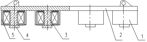
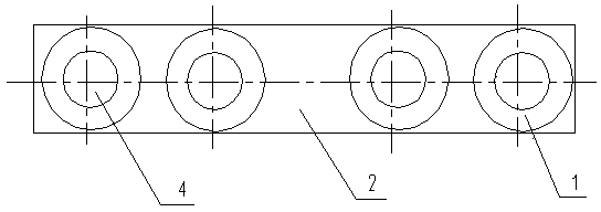
[0014] From figure 1 , figure 2 As can be seen, the U-shaped combined lifting electromagnet of the present invention includes an electromagnetic unit 1 and a yoke 2; the electromagnetic units 1 of the U-shaped combined lifting electromagnet are an even number, and at least four electromagnetic units 1 are arranged. Four electromagnetic units 1 are preferred. The coil of each electromagnetic unit 1 is mounted on the iron core 3, and the coil is packaged with a shell, and the circumferential shell 5 of the shell is not magnetically conductive. Stainless steel is preferably used as the circumferential shell 5 in the present invention. One end of the iron core 3 of the electromagnetic unit 1 is welded to the pole shoe 4, and the other end is fixedly connected to the yoke 2 with bolts, the axis of the iron core 3 is perpendicular to the yoke 2, and the iron core 3 is in good contact with the yoke 2; and from the yoke 2 ends, the magnetic polarity of the first electromagnetic uni...


PUM


Abstract

The invention discloses a U-shaped combined lifting electromagnet. The U-shaped combined lifting electromagnet comprises electromagnetic units and a magnet yoke. The number of the electromagnetic units is even number and at least equal to 4. One end of an iron core of each one of the electromagnetic units is fixedly connected to the magnet yoke. The axis of the iron core is perpendicular to the magnet yoke. From the electromagnetic unit fixedly connected to the end of the magnet yoke, each two electromagnetic units form a U-shaped electromagnet, and magnetic polarities of the two adjacent electromagnetic units of each two adjacent U-shaped electromagnets are the same. The electromagnetic units are connected to the magnet yoke by bolts. The U-shaped combined lifting electromagnet has the characteristics of low energy consumption, light deadweight and maintenance convenience.

Description

technical field [0001] The invention relates to an electromagnet, in particular to a lifting electromagnet. Background technique [0002] In my country's iron and steel production process, lifting electromagnets are widely used to lift billets and steel plates. However, the hoisting electromagnets used for hoisting steel billets and steel plates, especially for hoisting thick steel plates, are generally E-shaped structures, but this structure has a high energy consumption and a large dead weight. At present, there is a lifting electromagnet that adopts a plurality of electromagnetic units fixedly connected under a yoke plate, which actually constitutes a plurality of U-shaped electromagnets, which is more optimized in terms of energy consumption and self-weight than the E-shaped structure. But this kind of lifting electromagnet is that two adjacent electromagnetic units form a U-shaped electromagnet, so because the central electromagnetic unit has two adjacent electromagnet...

Claims


Application Information

Patent Timeline
Patent Type & Authority Applications(China)
IPC IPC(8): B66C1/06
Inventor 杨祖成代宋宁周洋
Owner 山东龙湖信息产业集团有限公司
Why Eureka
Try Eureka