Mechanical sealing device

A technology of mechanical sealing device and static ring, which is applied to mechanical equipment, components of pumping device for elastic fluid, machine/engine, etc. Affect the rotation of the moving ring, etc., to enhance the friction, ensure the sealing effect, and prolong the service life.

Active Publication Date: 2014-09-10
NINGBO DONGLIAN MECHANICAL SEAL
View PDF6 Cites 3 Cited by
  • Summary
  • Abstract
  • Description
  • Claims
  • Application Information

AI Technical Summary

Problems solved by technology

[0003] The utility model with authorized notification number CN201196263Y discloses a mechanical seal device, including a pump shaft, on which a pump chamber gland, a static ring, a moving ring, a spring bracket, and an impeller are sequentially arranged. The pump chamber gland has a concave The ring groove, the static ring is installed in the concave ring groove, the two ends of the static ring are respectively close to the concave ring groove and the end surface of the moving ring, the other end of the moving ring is fitted with the spring bracket, the spring bracket is tightly matched with the impeller, and the impeller Compress the spring bracket and drive the spring bracket and the moving ring to rotate in a circumferential direction. A housing cavity for accommodating the spring is opened on the outer wall of the spring bracket. The inner wall of the housing cavity is provided with a spring seat for fixing the spring. The outer wall of the moving ring is provided with The moving ring seat that fixes the moving ring and the spring support, this kind of mechanical seal device installs the moving ring seat on the outer wall of the moving ring, so that the moving ring and the spring support can rotate synchronously in the circumferential direction to realize the basic transmission of the machine, but in realizing the above At the same time, the mechanical seal device also has the following deficiencies: 1. Since the static ring is stationary, the moving ring moves on the end surface of the static ring, so the surface of the static ring is polished, but the polished surface of this static ring has only one side. Under the action of friction with the moving ring, it will gradually become rough and damaged, and the service life is short. When the static ring is damaged by friction, it must be replaced in time. The use is quite limited. If you continue to use it, the distance between the moving ring and the static ring The increase of friction will not only affect the rotation of the moving ring, but the static ring will also rotate with the moving ring, and the rotation of the static ring will increase the gap between the static ring and the sealing ring, which will also greatly affect the sealing effect of the sealing device; 2 . Since one end of the moving ring seat locks the moving ring, while the other end is only close to the outer wall of the spring bracket, during the long-term rotation of the impeller, a gap is likely to occur between the moving ring seat and the spring bracket, and the spring bracket There will also be relative movement with the pump shaft during the long-term rotation of the pump shaft, which is often referred to as "slipping". If there is a gap between the moving ring seat and the spring bracket at this time, the spring bracket is easy to separate from the moving ring. If the moving ring cannot be rotated, the transmission will fail, and the machine will not be able to achieve the normal transmission function.

Method used


Image

  • Mechanical sealing device
  • Mechanical sealing device
  • Mechanical sealing device

Examples


specific Embodiment approach

[0031] The following are specific embodiments of the present invention and in conjunction with the accompanying drawings, the technical solutions of the present invention are further described, but the present invention is not limited to these embodiments.

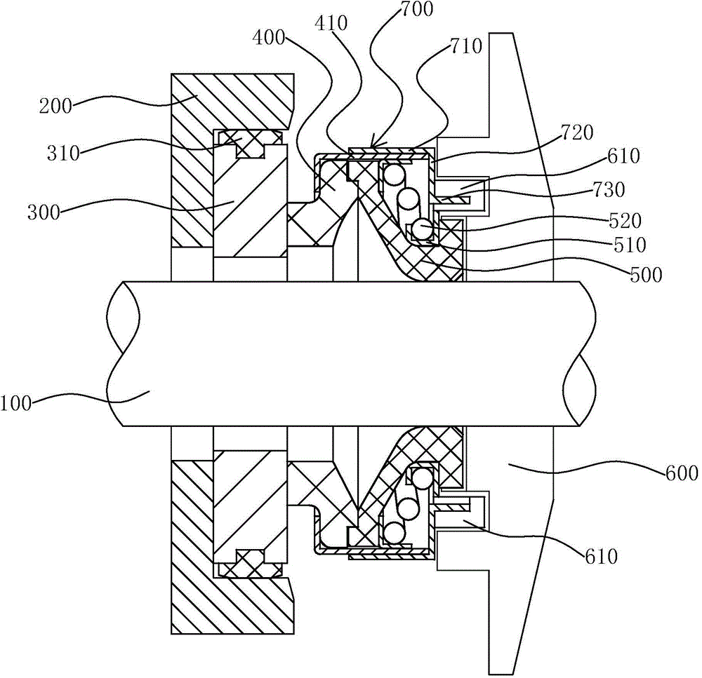
[0032] like figure 1 As shown, a mechanical sealing device of the present invention includes a pump shaft 100, on which a pump chamber gland 200 perpendicular to the pump shaft 100, a static ring 300, a moving ring 400, a spring bracket 500, and an impeller 600 are sequentially installed. .

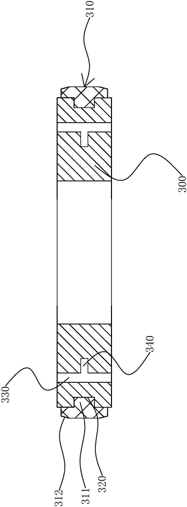
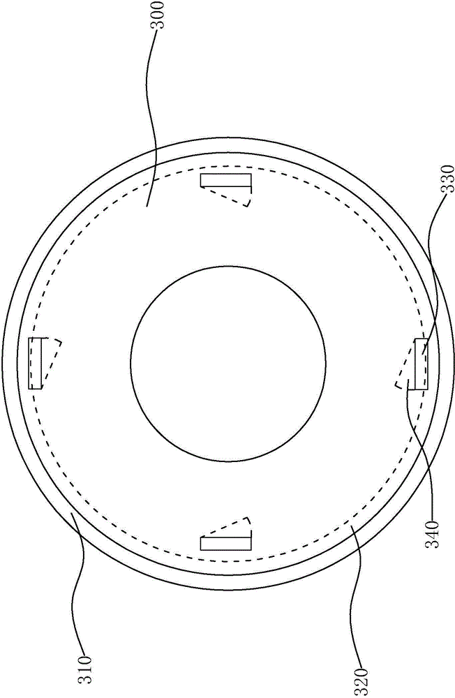
[0033] Further, a concave annular groove is axially opened on the end surface of the pump chamber gland 200 opposite to the moving ring 400, the static ring 300 is installed in the concave annular groove, and the two ends of the static ring 300 are respectively connected with the concave annular groove and the moving ring. 400 is close to one end face, and the end faces of the two ends of the static ring 300 are respectively polished...


PUM


Abstract

The invention provides a mechanical sealing device, belongs to the technical field of sealing systems, and aims at solving the technical problems of short service life of a static ring, large influence of damaged static ring on sealing effect, and easily-failed rotating of a dynamic ring of the existing mechanical sealing device. The mechanical sealing device comprises a pump shaft; a pump cavity pressing cover, a static ring, a dynamic ring and an impeller are sequentially arranged on the pump shaft; two ends of the static ring are respectively connected with the pump cavity pressing cover and one end surface of the dynamic ring; a dynamic ring seat is arranged on the dynamic ring; two end surfaces of the static ring are processed by polishing; a static ring sleeve, which is clung to the outer sidewall of the static ring and the pump cavity pressing cover, is arranged between the static ring and the pump cavity pressing cover; a fastening device is arranged on the dynamic ring seat; one end of the fastening device is clung to the dynamic ring seat and while the other end of the fastening device is fixedly connected with the impeller; the dynamic ring is rotated together with the impeller through the fastening device. With the adoption of the mechanical sealing device, the service life of the static ring is prolonged, the sealing effect is ensured, the fastening device is arranged to prevent a spring bracket and the pump shaft from oppositely rotating to cause failed transmission of the dynamic ring.

Description

technical field [0001] The invention belongs to the technical field of sealing systems, and relates to a mechanical sealing device. Background technique [0002] The mechanical seal device is a shaft seal device that relies on a pair or several pairs of end faces that are perpendicular to the shaft for relative sliding under the action of fluid pressure and the elastic force (or magnetic force) of the compensation mechanism, and is matched with an auxiliary seal to prevent leakage. Compared with other types of sealing devices, it has the advantages of high reliability, long service life, good mechanical friction, and wide adaptability, so it is widely used in various fields of life. [0003] The utility model with the authorization announcement number CN201196263Y discloses a mechanical sealing device, which includes a pump shaft, and a pump cavity gland, a static ring, a moving ring, a spring bracket and an impeller are arranged on the pump shaft in sequence, and the pump c...

Claims


Application Information

Patent Timeline
Patent Type & Authority Applications(China)
IPC IPC(8): F04D29/12
Inventor 李友宝励永平
Owner NINGBO DONGLIAN MECHANICAL SEAL
Why Eureka
Try Eureka