Bearing fixing structure

A fixed structure and bearing technology, applied in bearings, flexible bearings, bearing components, etc., can solve problems such as concentricity deviation, affecting the life of the overall motor, and shaft creep

Active Publication Date: 2014-09-10
ASIA VITAL COMPONENTS (CHINA) CO LTD
View PDF14 Cites 3 Cited by
  • Summary
  • Abstract
  • Description
  • Claims
  • Application Information

AI Technical Summary

Problems solved by technology

However, since the shaft center is connected to a rotor to be driven by the rotor, concentric deviation will occur when the rotor rotates. Moreover, the concentricity and unbalance of the rotor itself will easily cause the shaft center and the inner hole of the bearing, and the bearing and the Creep occurs between the shafts of the base, which will cause abnormal noise after long-term operation, which will affect the life of the overall motor
The so-called creep refers to the low-speed sliding wear caused by the relative motion between the bearing mating surfaces with loose fit or small interference. Although the sliding amount is extremely small, it occurs in places where it is difficult to apply lubrication. , so the amount of wear gradually increases until the bearing fails due to the loose fit of the outer ring
[0003] The latecomers propose such as Figure 1A and Figure 1B The two known structures shown, such as Figure 1A As shown, it includes a base 11 with a shaft cylinder 12 to accommodate a bearing 13, a shaft center 14 is inserted into an inner hole 131 of the bearing 13, and a shrapnel 14 is arranged in the shaft cylinder 12 and is located below the bearing 13, usually The setting of the shrapnel 14 is to provide pre-pressure to the bearing 13 to ensure that the bearing 13 is in a normal operating state, but the outer diameter of the bearing 13 shown in this figure is closely matched with the shaft cylinder 12 of the base 11. The bearing 13 is fixed by the shaft cylinder 12 and cannot move, so the shrapnel 14 cannot provide the preload of the bearing 13
in addition Figure 2B It shows that the outer diameter of the bearing 13 is loosely fitted with the shaft barrel 12 of the base 11, so that although the shrapnel 14 can provide preload to the bearing 13, when the shaft center 14 is running, the bearing 13 will wriggle. There is friction between the bearing 13 and the shaft tube 12 of the base 11, which will cause abnormal noise after long-term operation, and then affect the life of the overall motor

Method used


Image

  • Bearing fixing structure
  • Bearing fixing structure
  • Bearing fixing structure

Examples


Embodiment Construction

[0042] Hereinafter, the preferred implementation of the present invention will be described with reference to related drawings, in which the same components will be described with the same component symbols.

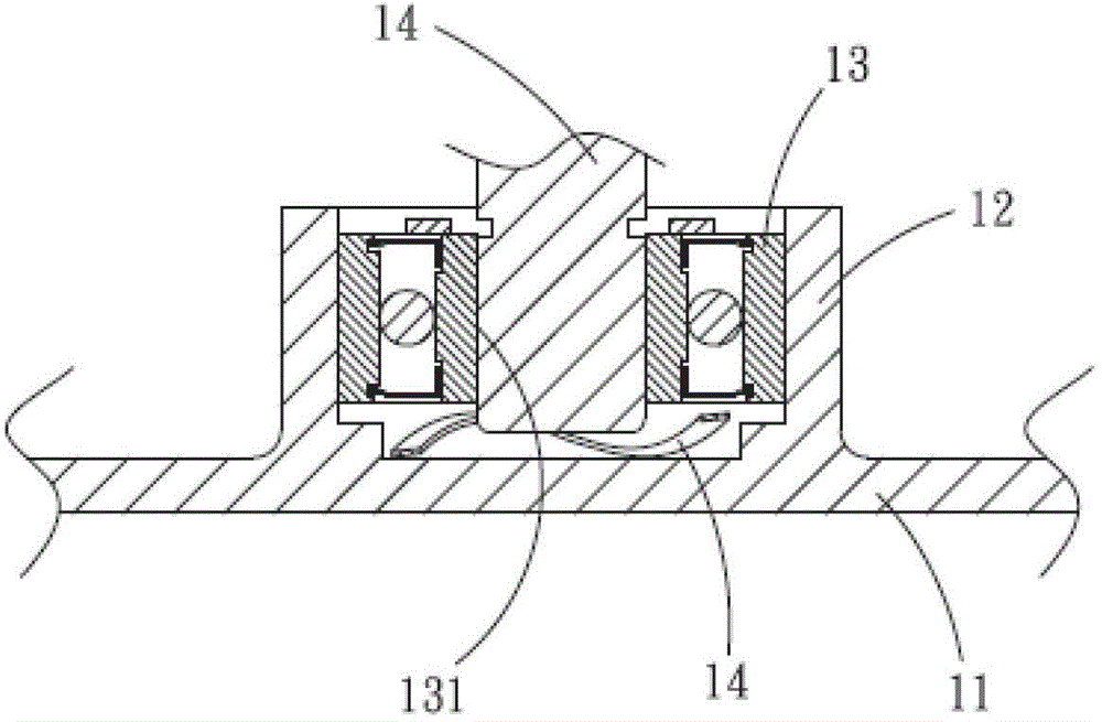
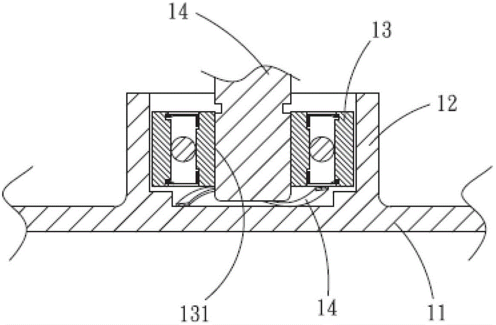
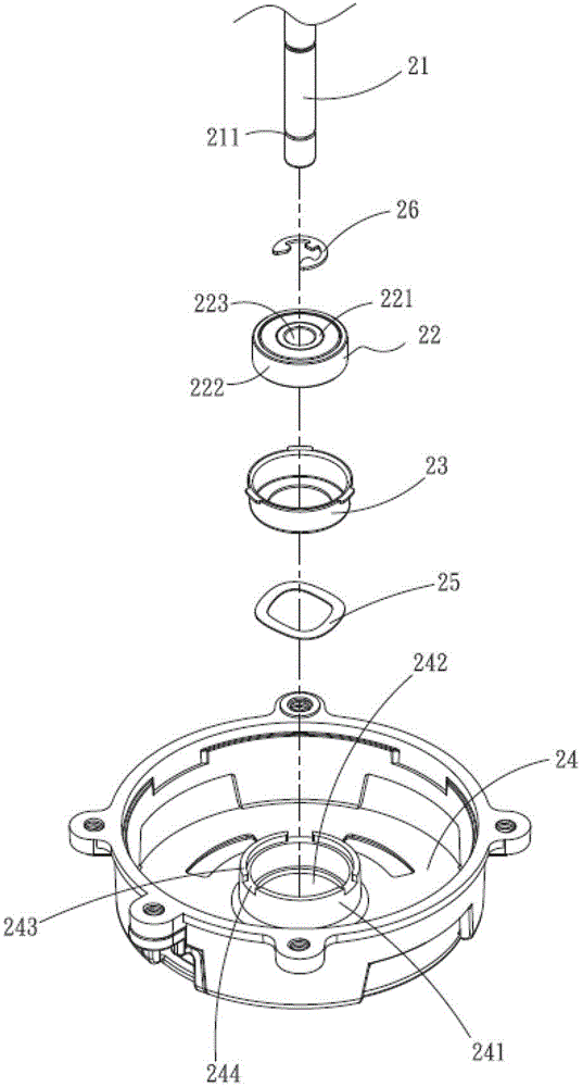
[0043] See Figure 2A and Figure 2B Shown, where Figure 2A Is a three-dimensional exploded schematic diagram of the present invention, Figure 2B It is a schematic cross-sectional view of the combination of the present invention. Such as Figure 2A As shown, it includes a shaft 21, a bearing 22, a bearing housing 23, a base 24, an elastic element 25 and a retaining ring 26. The bearing 22 has an inner ring 221 and an outer ring 222, and the inner ring 221 defines a bearing inner hole 223.

[0044] Reference together image 3 As shown, the bearing housing 23 has an annular bottom 231 defining a hollow through hole 232 for inserting the shaft 21, the outer edge of the annular bottom 231 extends upward to form a side 233, the side 233 has a first A free end 234, the annular b...


PUM


Abstract

A bearing fixing structure comprises a bearing arranged in a shaft tube of a pedestal. The bearing has a close fit plug connection with a shaft center. A bearing fixing shell for accommodating the bearing is arranged between the bearing and the shaft tube. The bearing closely cooperates with the bearing fixing shell. The bearing fixing shell loosely cooperates with the shaft tube. The shaft tube has a at least one radial spacing portion, and the radial spacing portion abuts the at least one lug of the bearing fixing shell to restrict the radial rotation of the bearing fixing shell. An elastic element is arranged in the shaft tube, and is positioned below the bearing fixing shell in order to provide a preload pressure for the bearing fixing shell.

Description

Technical field [0001] The present invention is a bearing fixing structure, in particular to a bearing fixing structure applied to a motor. Background technique [0002] The generally known bearing structure is to place the bearing directly in a shaft barrel of a base, and then a shaft is inserted into an inner hole of the bearing, wherein the shaft and the inner hole of the bearing fit in a loose fit. An outer diameter of the bearing fits with the shaft barrel in a loose fit. However, because the shaft is connected to a rotor to be driven by the rotor, concentric deviations will occur when the rotor rotates. Moreover, the concentricity and imbalance of the rotor itself will easily cause the shaft and the bearing inner hole, and the bearing and the The phenomenon of creeping between the shaft and cylinder of the base will cause abnormal noise after long-term operation, which will affect the life of the overall motor. The so-called creeping refers to the low-speed sliding wear c...

Claims


Application Information

Patent Timeline
IPC IPC(8): F16C27/00H02K5/173H02K5/24F04D29/05F04D29/66
Inventor 苗茂科锺文主黄井平
Owner ASIA VITAL COMPONENTS (CHINA) CO LTD
Why Eureka
Try Eureka