Device for venting gear units

一种变速器、变速器壳体的技术,应用在机械设备、传动装置零件、皮带/链条/齿轮等方向,能够解决变速器轴机械加工有要求、限制扭矩载荷、耗费成本等问题

Inactive Publication Date: 2014-09-10
SIEMENS AG
View PDF6 Cites 0 Cited by
  • Summary
  • Abstract
  • Description
  • Claims
  • Application Information

AI Technical Summary

Problems solved by technology

The disadvantage of this venting method is that it requires machining of the transmission shaft
This is costly and limits the permissible torque load on the shaft

Method used


Image

  • Device for venting gear units
  • Device for venting gear units
  • Device for venting gear units

Examples


Embodiment Construction

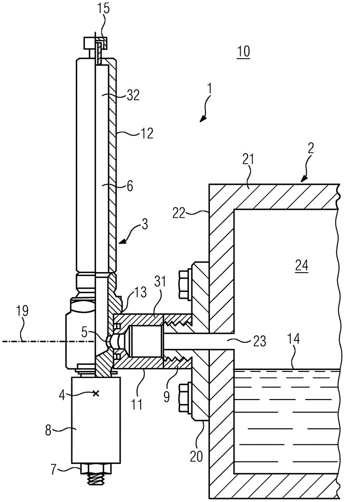
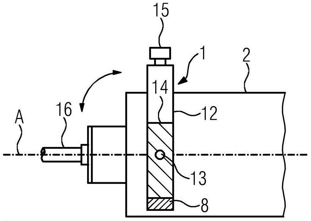
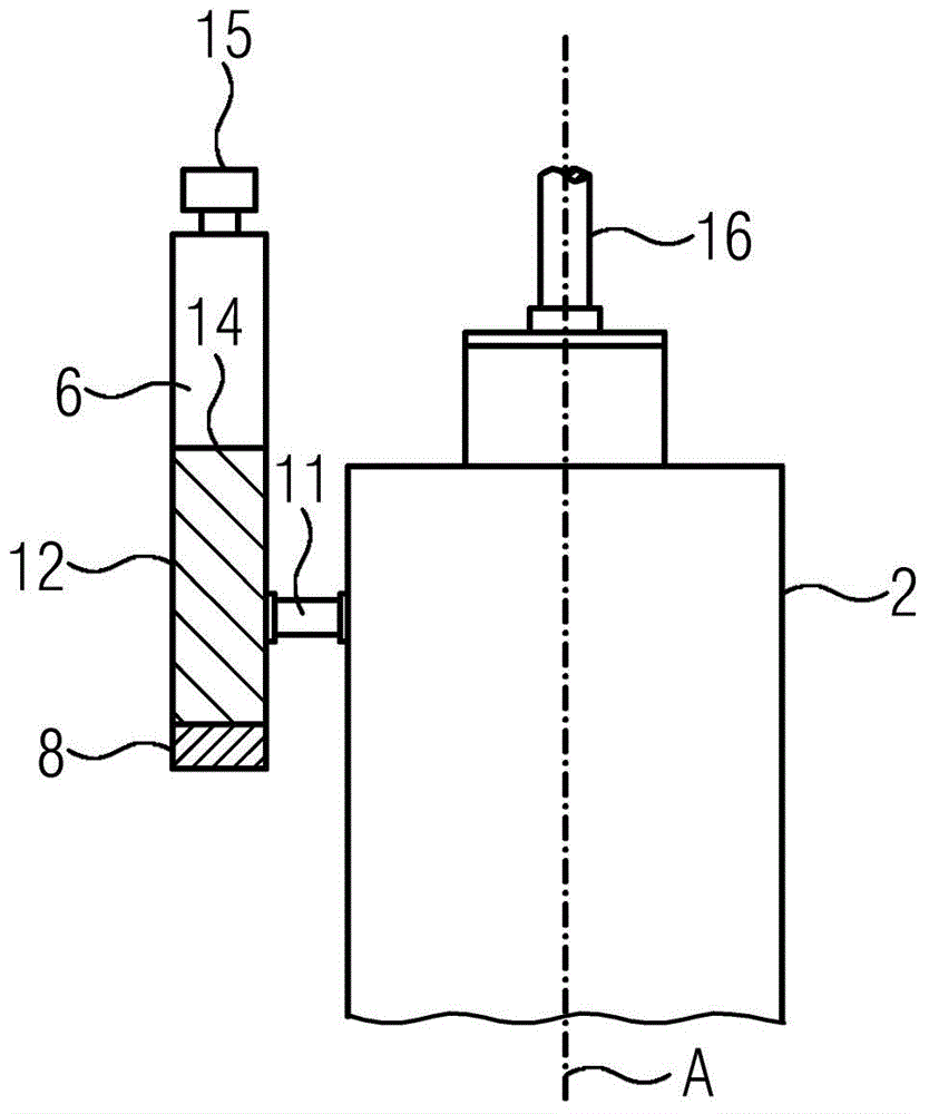
[0037] figure 1 A device 1 for venting a transmission 2 operated with oil immersion lubrication is shown. The device 1 comprises a tubular first part 11 and a tubular second part 12 which is substantially longer than the first part 11 . The second part 12 comprises an elongated thin-walled tube which is used as the compensation container 6 . On one end of the second part 12 a thick steel plate 8 is carried, which is firmly connected to the compensating container 6 by means of a screw arrangement 7 .

[0038] At its transmission-side end, the first part 11 has an internal thread 9 which is screwed securely onto an external thread of a screw flange 20 which is arranged on an outer side 22 of the transmission 2 . The two parts 11 and 12 are connected and movable relative to each other by means of a hinge 13 . The hinge 13 is designed as an axially rotating sleeve, for example a linearly rotating sleeve supported on a ball bearing, that is to say that the second part 12 can rot...


PUM


Abstract

The invention relates to a device (1) for venting gear units (2). The device (1) comprises a first component (11) and a second component (12) which are respectively connected to each other by a joint (13). The first component is fixed to a transmission assembly (2). A pipeline (3) extending along the components (11, 12) is provided such that an air exchange between a first end part (31) of the first component (11) and a second end part of the second component (12) is possible. A center of gravity (4) of the second component (12) with respect to a connection point (5) of the joint (13) is made opposite to the second end part (32) of the pipeline (3) at the second component (12).

Description

technical field [0001] The invention relates to a device for venting a transmission and a transmission with such a device. Background technique [0002] The loss of heat from the transmission causes temperature oscillations in the transmission housing. The internal pressure in the transmission housing then changes as a result of temperature oscillations. Pressure differences between the housing interior and the housing surroundings are compensated. [0003] For a transmission in which the direction of the lubricant level remains constant relative to the transmission shaft during operation, venting can be realized in a simple manner via the vent valve, which is arranged at A location on the transmission housing above the lubricant level. Conversely, the valve cannot be used when the variator is swinging or even rotated 360 degrees, because based on the position change of the variator, the valve may reach below the lubricant level and the lubricant may thus be drawn from th...

Claims


Application Information

Patent Timeline
Patent Type & Authority Applications(China)
IPC IPC(8): F16H57/027F16H57/04
CPCF16H57/027F16H57/0454Y10T74/2189
Inventor 斯特凡·海涅乌韦·克雷默托马斯·施托伊贝勒
Owner SIEMENS AG
Why Eureka
Try Eureka