Fatigue cracking simulation testing method and apparatus for seamless expansion joint material of bridge

A technology of seamless expansion and fatigue cracking, applied in the direction of applying repeated force/pulsation force to test the strength of materials, to achieve the effect of accurate real service performance and service life

Inactive Publication Date: 2014-09-10
WUHAN UNIV OF TECH
View PDF4 Cites 14 Cited by
  • Summary
  • Abstract
  • Description
  • Claims
  • Application Information

AI Technical Summary

Problems solved by technology

At present, my country has not yet formed a corresponding standard for the testing of bridge seamless expansion joint materials and structural performance. Material optimization and scientific evaluation of its service life

Method used


Image

  • Fatigue cracking simulation testing method and apparatus for seamless expansion joint material of bridge
  • Fatigue cracking simulation testing method and apparatus for seamless expansion joint material of bridge
  • Fatigue cracking simulation testing method and apparatus for seamless expansion joint material of bridge

Examples


Embodiment 1

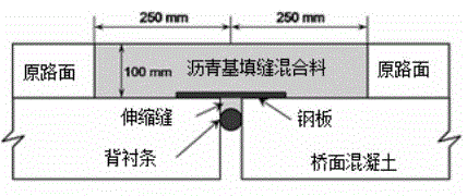
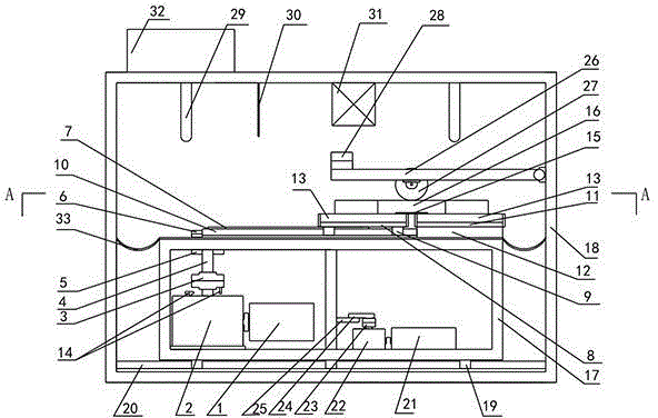
[0066] Place the concrete member 13 on the first steel plate 8 of the test platform, fix it on the second steel plate 11, lay the third steel plate (thin-layer steel plate) 15 directly above the joint (ie bridge seamless expansion joint) 35, and place the The bridge seamless expansion joint material (modified asphalt binder: aggregate mass ratio = 1:5) 16 is paved in 2 concrete members 13 to make a test piece (length 500mm×width 400mm×thickness 100mm). After curing for 24 hours, place the solid rubber tire 27 on the surface of the test piece 16, adjust the counterweight 28 so that the wheel pressure is 0.7MPa, the relative travel distance between the tire 27 and the test piece 16 is 50cm, and the traveling speed is 2.0km / h . The rotation radius of the first crank 6 is adjusted, the horizontal stretching distance of the test piece 16 is 10 mm, and the relative reciprocating motion speed between the first steel plate 8 and the second steel plate 11 is 50 mm / min. Open the contro...

Embodiment 2

[0068] Place the concrete member 13 on the first steel plate 8 of the test platform, fix it on the second steel plate 11, lay the third steel plate (thin-layer steel plate) 15 directly above the joint (ie bridge seamless expansion joint) 35, and place the The bridge seamless expansion joint material (modified asphalt binder: aggregate mass ratio = 1:3) 16 is paved in 2 concrete members 13 to make a specimen (length 700mm×width 400mm×thickness 100mm). After curing for 24 hours, place the solid rubber tire 27 on the surface of the test piece 16, adjust the counterweight 28 so that the wheel pressure is 2.0MPa, the relative travel distance between the tire 27 and the test piece 16 is 70cm, and the traveling speed is 3.0km / h . The rotation radius of the first crank 6 is adjusted, the horizontal stretching distance of the test piece 16 is 70 mm, and the relative reciprocating motion speed between the first steel plate 8 and the second steel plate 11 is 100 mm / min. Turn on the temp...


PUM


Abstract

The invention relates to a fatigue cracking simulation testing method and apparatus for a seamless expansion joint material of a bridge. The testing method comprises the following steps: 1) placing two concrete members on a test platform and fixing the two concrete members to prepare an expansion joint structure with a groove; 2) paving a to-be-tested bridge seamless expansion joint material in the groove of the expansion joint structure so as to prepare a test piece; 3) setting testing temperature and maintaining the test piece at a constant temperature; 4) placing a tire on the surface of the test piece, adjusting wheel pressure and the relative travel distance and speed between the tire and the test piece and allowing the test piece and the tire to carry out relative reciprocating motion; 5) allowing the two concrete members to carry out relative reciprocating motion; and 6) measuring the tensile deformation of the bridge seamless expansion joint material and respectively recording the numbers of relative reciprocating motions of the concrete members and the tire during initial cracking and final cracking of the bridge seamless expansion joint. The testing method and apparatus can be used for determination of repeated loading frequencies needed by fatigue cracking of the bridge seamless expansion joint material under the action of both tire loading and bridge temperature contraction.

Description

technical field [0001] The present invention relates to a bridge seamless expansion joint material fatigue cracking simulation test method and its test equipment, in particular to a fatigue cracking simulation test method for small and medium-sized bridge seamless expansion joint materials under the joint action of tire load and bridge temperature shrinkage and its testing equipment. Background technique [0002] Bridge expansion joints are an important part of bridge design. It is a device that can be relatively freely deformed between the beam ends of the bridge structure or other appropriate positions to meet the expansion and deformation of the bridge. Bridge expansion joints directly bear the impact of traffic loads in the bridge structure, and are exposed to the air for a long time. The use environment is harsh, easy to damage and high maintenance cost. In the bridge structure, the expansion joint is a relatively small and cheap part. Its design, material selection an...

Claims


Application Information

Patent Timeline
Patent Type & Authority Applications(China)
IPC IPC(8): G01N3/32
Inventor 磨炼同刘爽谢严君束冬林王慧丰吴少鹏
Owner WUHAN UNIV OF TECH
Why Eureka
Try Eureka