Double-circuit line non-in-phase cross-line earth fault judgment method based on trigonometric function

A double-circuit line, grounding fault technology, applied in the fault location and other directions, can solve the problems of power failure, inability to eliminate zero-sequence mutual inductance between lines, large power flow transfer, etc., to achieve elimination of influence, high fault discrimination accuracy, and enhanced accuracy Effect

Active Publication Date: 2014-09-10
STATE GRID PUTIAN ELECTRIC POWER SUPPLY +3
View PDF8 Cites 10 Cited by
  • Summary
  • Abstract
  • Description
  • Claims
  • Application Information

AI Technical Summary

Problems solved by technology

Since the origin of the coordinates is located on the boundary of the action characteristic circle, there is a possibility of misoperation for a ground fault at the outlet in the opposite direction of protection, and the larger the transition resistance is, the easier it is for the protection to malfunction when there is a ground fault at the outlet in the opposite direction.
[0005] Due to the strong zero-sequence mutual inductance between double-circuit lines on the same pole, the existing grounding distance protection cannot obtain the zero-sequence current of the other circuit, and the algorithm model cannot eliminate the influence of zero-sequence mutual inductance between lines. Due to the influence of zero-sequence mutual inductance, when the traditional grounding distance protection is applied to parallel double-circuit lines on the same pole, its protection range will be greatly expanded. Faults in the protection setting range often have steady-state overshoots, which makes it easy to malfunction when faults outside the protection area. It is easy to cause a large transfer of power flow and cause large-scale power outages

Method used


Image

  • Double-circuit line non-in-phase cross-line earth fault judgment method based on trigonometric function
  • Double-circuit line non-in-phase cross-line earth fault judgment method based on trigonometric function
  • Double-circuit line non-in-phase cross-line earth fault judgment method based on trigonometric function

Examples


Embodiment Construction

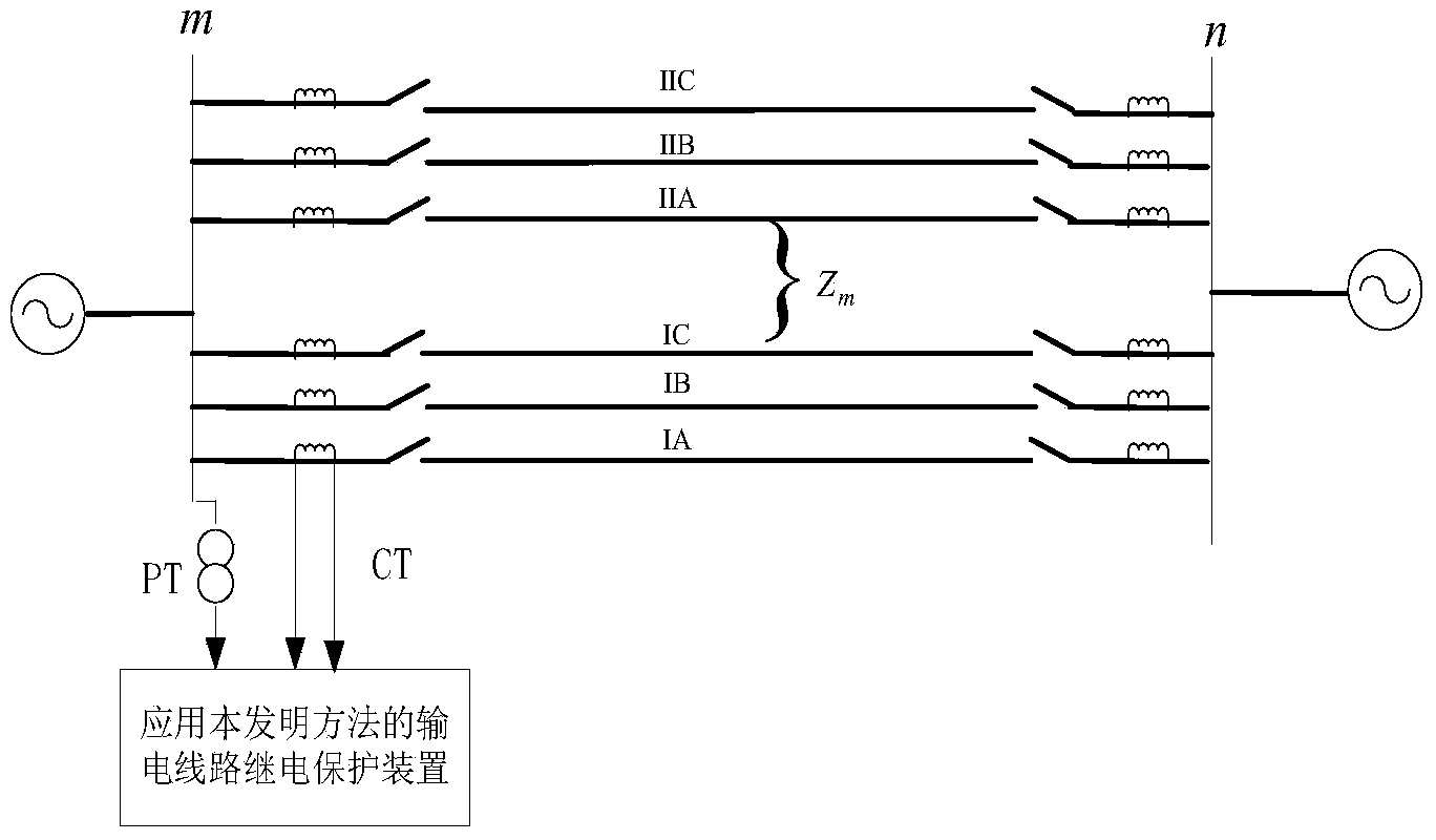
[0025] Such as figure 1 As shown, the protection device measures the fault phase voltage at the installation place of the I-circuit line protection of the parallel double-circuit line on the same pole fault phase current and zero sequence current Among them, φ is the phase A of the I-circuit line, the phase B of the I-circuit line, or the phase C of the I-circuit line. figure 1 Among them, PT is a voltage transformer; CT is a current transformer.

[0026] The protection device calculates the zero-sequence current of the double-circuit line II on the same pole parallel:

[0027] I · II 0 = I · I 0 ( - cos ( r 1 + r ...


PUM


Abstract

The invention discloses a double-circuit line non-in-phase cross-line earth fault judgment method based on a trigonometric function. The method comprises the steps that the fault phase voltage, the fault phase current and the zero-sequence current at the protection installing position of the line I of same-tower double-circuit lines are firstly measured the zero-sequence compensating current of the line I of the same-tower double-circuit lines is calculated, the phase angle of the fault phase voltage of the protection installing position of the line I of the same-tower double-circuit lines ahead of the zero-sequence current injected in a non-in-phase cross-line earth fault point is calculated, the fault phase voltage of the line I of the same-tower double-circuit lines within the protection setting range is calculated, and the accurate judgment on a double-circuit line non-in-phase cross-line earth fault is achieved through the amplitude characteristic of the trigonometric function of the vector relation between electrical quantities of single ends after the double-circuit line non-in-phase cross-line earth fault happens. The judgment result is not influenced by factors such as zero-sequence mutual inductance between lines, transition resistance, load currents and electric power system operation modes, and the double-circuit line non-in-phase cross-line earth fault judgment method based on the trigonometric function is applicable to same-tower double-circuit line single-end electric quantity backup protection.

Description

technical field [0001] The invention relates to the technical field of electric power system relay protection, in particular to a method for discriminating grounding faults of non-identical phases across lines of double-circuit lines based on trigonometric functions. Background technique [0002] The double-circuit line paralleled on the same pole has a small footprint, low cost, and stable and reliable operation when connected to the grid. It has become a common transmission line connection method in the power system. There is zero-sequence mutual inductance between double-circuit lines on the same pole, and the zero-sequence mutual inductance affects the zero-sequence compensation coefficient, thereby generating additional impedance. The additional impedance caused by the zero-sequence mutual inductance will cause the fault impedance measured by the protection device to be greater than the actual fault When a ground fault occurs near the protection setting range in the dou...

Claims


Application Information

Patent Timeline
Patent Type & Authority Applications(China)
IPC IPC(8): G01R31/08
Inventor 曾惠敏
Owner STATE GRID PUTIAN ELECTRIC POWER SUPPLY
Why Eureka
Try Eureka