Experimental device of feeding mechanism of linear motor
A feed mechanism and linear motor technology, applied in the field of linear motor feed mechanism testing, can solve problems such as high control performance requirements, strict protection, and heat generation.
- Summary
- Abstract
- Description
- Claims
- Application Information
AI Technical Summary
Problems solved by technology
Method used
Image

Examples
Embodiment 1
[0029] Example 1 An experimental device for a linear motor feed mechanism
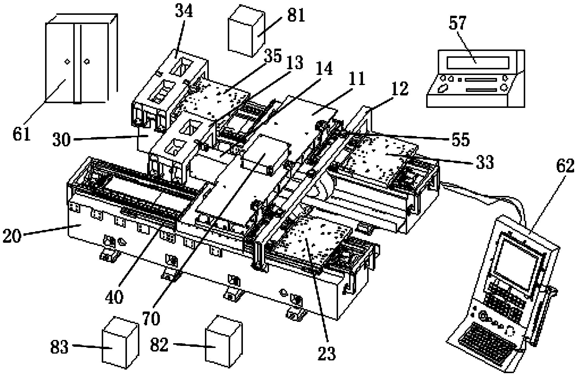
[0030] like Figure 1-Figure 4 As shown, a linear motor feed mechanism experimental device
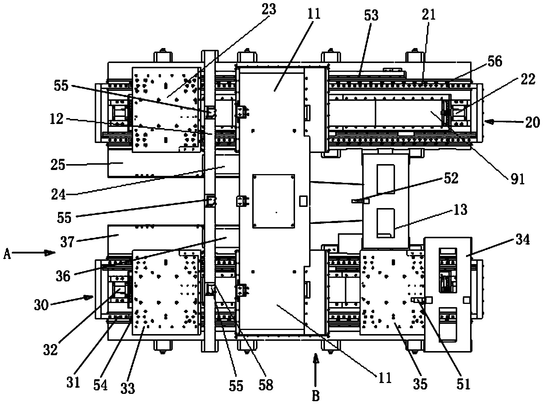
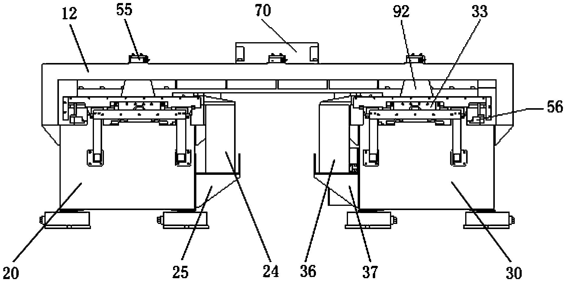
[0031] The connecting plate (11) is bridged on the base I (20) and the base II (30), and its two ends are respectively connected to the base I (20) and the base II (30) through slideways (40). The measuring instrument bracket (12) is bridged on the base I (20) and the base II (30), and the two ends of the support frame I (13) are respectively fixed with the base I (20) and the base II (30), and the support The frame I (13) is movably connected with the connecting plate (11) through the connecting body (14).
[0032] The base I (20) is provided with two guide rails I (21), the two ends of the base I (20) are provided with buffer I (22), and the slide plate I (23) is slidingly connected with the guide rail I (21).
[0033] The base II (30) is provided with two guide rails II (31), the two ends of the base II (...
Embodiment 2
[0043] Embodiment 2 A method for testing the performance of a linear motor feed mechanism
[0044] Adopt the linear motor feeding mechanism experimental device of embodiment 1, test method is as follows:
[0045] 1) Single linear motor thrust and thrust fluctuation test method
[0046]Install the secondary (91) of the linear motor to be tested in the two guide rails II (31) on the base II (30), the primary (92) of the linear motor to be tested is fixed on the lower end of the connecting plate (11) and connected with One end of the slide plate III (35) is fixed, and the tension and pressure sensor (51) is installed on the support frame II (34) as a load on the drive end of the linear motor. The electrical cabinet (61) and the control system (62) drive the linear motor to run, and the support frame II (34) is fixed to the slide plate III (35) for detection (at this time, the support frame I (13) is not connected to the connecting plate (11)), through the tension and pressure se...
PUM
 Abstract
Description
Claims
Application Information
 - R&D Engineer
- R&D Manager
- IP Professional
- Industry Leading Data Capabilities
- Powerful AI technology
- Patent DNA Extraction
Browse by: Latest US Patents, China's latest patents, Technical Efficacy Thesaurus, Application Domain, Technology Topic.
© 2024 PatSnap. All rights reserved.Legal|Privacy policy|Modern Slavery Act Transparency Statement|Sitemap