110 kv line two-circuit iron tower equipotential swing ladder

A double-circuit, equipotential technology, applied to overhead lines/cable equipment, ladders, buildings, etc., can solve the problems of inability to carry out live work, fail to meet the requirements of combined gaps, and fail to meet safety requirements, etc., to improve the quality of power supply services , Guarantee operation safety and reduce the effect of less power transmission

Inactive Publication Date: 2014-09-10
STATE GRID CORP OF CHINA +1
View PDF0 Cites 0 Cited by
  • Summary
  • Abstract
  • Description
  • Claims
  • Application Information

AI Technical Summary

Problems solved by technology

[0003] Due to the small structural size of the 110kV double-circuit corner tower, it does not meet the necessary conditions for the hanging basket method; and the effective insulation length of the 110kV insulator is generally 1.2 meters, which does not meet the requirements of entering the strong electric field combination gap along the insulator string; at the same time , 110kV double-circuit tower conductors are arranged vertically, the distance between phases is 3.0 meters, the length of the aluminum alloy soft ladder used for equipotential work by hanging body method is 1.2 meters, plus the height of the operators, the operators use hanging bodies for the middle and upper phase conductors The minimum distance between adjacent phase conductors does not meet the requirements of the regulations during the process of entering the strong electric field by the method; if the flat ladder method is used to enter the strong electric field, the combined gap between the human body and the inner corner side cross arm and conductors does not meet the safety requirements
After investigation, it was found that there is no special tool for equipotential work on the double-circuit iron tower of 110kV line in the market at present. The power outage of the line has seriously affected the reliability of the transmission facility

Method used


Image

  • 110 kv line two-circuit iron tower equipotential swing ladder

Examples


Embodiment Construction

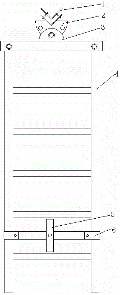
[0013] like figure 1 As shown, the present invention is a 110kV line double-circuit iron tower equipotential swing ladder, including an insulating hard ladder 4, and its length is required to be no less than 3m. A connecting rod is fixedly installed on the top of the insulating hard ladder 4, specifically, a casing is respectively provided at both ends of the connecting rod, and one end of the insulating hard ladder 4 extends into the casing and passes through the fastener and the casing. Fixed connection.

[0014] A U-shaped chuck 3 is arranged in the middle of the connecting rod, and a mounting hole is respectively opened on the opposite ends of the U-shaped chuck 3, and a half-circular plate 2 is also included. There are 3 through holes on the top, and the semicircular plate 2 is inserted into the middle of the U-shaped chuck 3 through any one of the through holes and fixed on the mounting hole of the U-shaped chuck 3 with fasteners. The interval between any two adjacent ...


PUM


Abstract

The invention relates to a 110kV line two-circuit iron tower equipotential swing ladder which is characterized by including an insulating rigid ladder (4), a connecting rod is fixedly installed on the top end of the insulating rigid ladder (4), the middle parts of the connecting rod (4) is provided with a U type clamping head (3), installation holes are respectively arranged on two opposite ends of the U type clamping head (3), the110kV line two-circuit iron tower equipotential swing ladder also includes a semi- circular plate (2), the arc part of the semi-circular plate (2) is provided with three through holes, the semi-circular plate (2) is fixed on a mounting hole of the U type clamping head (3) by a fastener passing through arbitrary through hole, a first angle iron is fixedly installed on the linear part of the semi- circular plate (2), and the first angle iron is detachably connected with a second angle iron (1)by a fastener. The 110kV line two-circuit iron tower equipotential swing ladder solves the problems that during equipotential hot-line work of middle and upper phases in a 110kV two-circuit iron tower, complex gap and distance between an adjacent-phase conductive wire and an operating personnel cannot be met.

Description

technical field [0001] The invention relates to an equipotential swinging ladder of a 110kV line double-circuit iron tower. Background technique [0002] In recent years, with the improvement of power grid management level, the requirements for the reliability of power transmission facilities are also getting higher and higher. Since temporary power outages will cause unplanned power outages on the line, which will seriously affect the reliability of power transmission and transformation facilities and the quality of power supply services, live-line work is generally used for emergency shortfall work. Live work is divided into three ways: equipotential, ground potential and intermediate potential. When dealing with defects on wires, equipotential operation is generally used. According to the "Safety Work Regulations of State Grid Corporation (Line Part)", the minimum combined gap of 110kV in equipotential operation is 1.2 meters; the minimum distance between equipotential ...

Claims


Application Information

Patent Timeline
Patent Type & Authority Applications(China)
IPC IPC(8): H02G1/02E06C1/04E06C7/48E06C7/46
Inventor 毛吉贵杨志宁马学荣高幸李力邓凯强荣
Owner STATE GRID CORP OF CHINA
Why Eureka
Try Eureka