Ethernet network standby power supply module, device and system

A technology of backup power supply and Ethernet, applied in the direction of data switching current source, data exchange details, etc., can solve the problems of inability to operate, increase material and installation labor costs, lack of separation of power supply and data, and achieve the effect of avoiding power failure

Inactive Publication Date: 2014-09-10
CONNECTING HOUSE SYST
8 Cites 17 Cited by

AI-Extracted Technical Summary

Problems solved by technology

[0005] (2) Because traditional IP equipment requires an external power supply, there must be an AC power socket within the range of the power supply cable where the IP equipment is installed. Otherwise, an AC power supply must be specially installed, and the need to arrange an AC power supply will increase additional materials and installation labor. cost, these costs can be saved for the installation of PoE equipment
[0006] (3) Traditional IP equipment requires an external 110VAC-240VAC external power supply, which cannot be used in many special places such as humid environments, dusty and explosive environments, outdoor environments, or where it ...

Method used

As shown in Figure 3, be in a factory that uses Ethernet power supply network, connected 4 PoE/IP cameras, because the needs of production, four PoE/IP cameras must transmit important monitoring images in real time, However, due to the unstable supply voltage, unpredictable power outages and daily power cut measures that often occur in summer, important monitoring images are unstable or lost. Therefore, the factory switched to an IP/PoE camera with internal storage SD card, and equipped with this backup power supply device to completely avoid troubles and losses caused by unstable voltage or power failure.
PoE splitter can be separated by the data flow that the power supply that PoE switch (or other PoE equipment) prov...

Abstract

The invention discloses an Ethernet network standby power supply module, a device and a system, and relates to the technical field of power supply devices and systems. The standby power supply module comprises a power supply monitoring and display module, a battery and protection circuit module, and a power output voltage-stabilizing and voltage-boosting module, wherein the power supply monitoring and display module is used for monitoring inputted power supply, displaying the working state of the power supply and the value of the inputted power supply, and carrying out charging or discharging control on the battery; the battery and protection circuit module is used for receiving the power supply outputted by the power supply monitoring and display module and the battery carries out charging or discharging; and the power output voltage-stabilizing and voltage-boosting module is used for receiving the power supply outputted by the power supply monitoring and display module or the battery and protection circuit module and outputting the power supply after voltage-stabilizing and voltage-boosting processing to the module in need of power supply. As the standby power supply module is used and a POE (Power Over Ethernet) separator or a POE injector is configured, uninterrupted power supply can be provided for the IP equipment or the POE equipment in the Ethernet network, and running stability of the equipment is improved.

Application Domain

Data switching current supply

Technology Topic

InjectorPower over Ethernet +6

Image

  • Ethernet network standby power supply module, device and system
  • Ethernet network standby power supply module, device and system
  • Ethernet network standby power supply module, device and system

Examples

  • Experimental program(1)

Example Embodiment

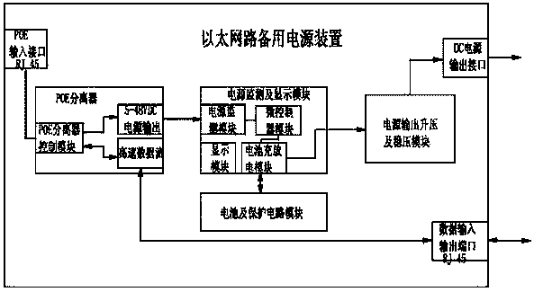
[0034] The PoE splitter can separate the power provided by the PoE switch (or other PoE devices) and the data flow transmitted through the network cable. The data flow and the power supply flow out from different interfaces respectively. The power supply continuously powers the battery in the backup power module without the need to remove DC power from a nearby AC power source through an adapter to charge the battery. In some special occasions, for example, when there is no PoE switch, but only a traditional Ethernet switch, the DC power required for charging can also be obtained from the nearby AC power supply through the included or external power adapter, and by using The POE splitter can also ensure that high-speed data streams can be transmitted accurately and without error.
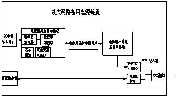
[0035] The PoE injector can integrate the power 48VDC (55VDC) provided by the AC power supply through the AC-DC conversion adapter and the high-speed data stream transmitted by the Ethernet switch (or router or other similar equipment) into a PoE network cable. By integrating the POE injector into the present invention, the original traditional Ethernet can be transformed into a new generation of Ethernet power supply network after passing through the backup power supply module. The present invention has an additional benefit of providing a stable supply voltage capability. Because the power of the backup power module is provided by the battery, even if the external power supply is unstable, the output voltage of the backup power module will not be affected.
[0036] The technical solutions in the embodiments of the present invention will be clearly and completely described below with reference to the accompanying drawings in the embodiments of the present invention. Obviously, the described embodiments are only a part of the embodiments of the present invention, rather than all the embodiments. Based on the embodiments of the present invention, all other embodiments obtained by those of ordinary skill in the art without creative efforts shall fall within the protection scope of the present invention.
[0037] Many specific details are set forth in the following description to facilitate a full understanding of the present invention, but the present invention can also be implemented in other ways different from those described herein, and those skilled in the art can do so without departing from the connotation of the present invention. Similar promotion, therefore, the present invention is not limited by the specific embodiments disclosed below.
[0038] The invention provides an Ethernet circuit backup power supply module. The backup power supply module cooperates with a POE separator or a POE injector to form an Ethernet circuit backup power supply device, and is used in cooperation with other equipment by using the Ethernet circuit backup power supply device. Constitute a new Ethernet power supply network system.
[0039] like figure 1 As shown in or 2, an Ethernet circuit backup power supply module, including a power supply monitoring and display module, is used to monitor the input power supply, display the working state of the power supply and the value of the input power supply, and control the charging or discharging of the battery; the battery and The protection circuit module is used to receive the power output from the power monitoring and display module, and the battery is charged or discharged; the power output voltage regulator and boost module is used to receive the power output from the power monitoring and display module or the battery and the protection circuit module, and the After the power supply is regulated and boosted, it is output to the module that needs power supply.
[0040] like figure 1 As shown in or 2, the power monitoring and display module includes a power monitoring module, which is used to monitor the input power supply and process the information of the power supply and output it to the microcontroller module; the microcontroller module is used to process the data collected by the power supply monitoring module. power supply information and output instructions to the battery charging and discharging module and display module according to the information; the battery charging and discharging module is used to receive the instructions output by the microcontroller module and perform charging and discharging processing on the battery according to the instructions; the display module is used to receive the micro-controller module. Power supply information output by the controller module, and display the information.
[0041] The present invention provides two Ethernet circuit backup power supply devices. The first one is as follows: figure 1 As shown, an Ethernet circuit backup power supply device made by using the backup power supply module of the present application is provided, which includes the backup power supply module described in the text, and also includes a POE input interface, a POE splitter and a DC power output interface. The POE The input interface is an RJ45 interface, the POE input interface is connected with the input end of the POE splitter, the power output end of the POE splitter is connected with the input end of the backup power supply module, and the power output end of the backup power supply module is connected with the DC power supply Output interface connection.
[0042] The second such as figure 2 As shown, an Ethernet circuit backup power supply device made by using the backup power supply module of the present application is provided, including the backup power supply module described in the text, and also includes a DC power supply input interface and a POE injector, the DC power supply input interface and The power input end of the backup power module is connected, and the power output end of the backup power module is connected with the power input end of the POE injector.
[0043] The backup power module preferably uses a lithium battery. The standard voltage of the lithium battery is 3.7V. In order to charge the battery, the 48VDC (55VDC) provided by PoE must first be reduced to 5V by a step-down circuit (which can be adjusted according to the battery and conditions). Adjustment). The fast charging and buffer circuit of the lithium battery can fully charge the fully discharged battery within the safe range and the shortest time possible. And when fully charged, it can continue to maintain the battery's power with a very small current.
[0044] Because different IP devices or PoE devices will use different working voltages, such as the common 3.3VDC/5VDC/9VDC/12VDC/24VDC/48VDC. These working voltages from low voltage to 48V, except that the working voltage lower than 3.7V battery voltage does not require an additional booster circuit, other working voltages higher than 3.7V need to use the booster circuit to convert the battery The voltage is raised to the specified voltage.
[0045] like figure 1 As shown, the device of the present invention needs to be switched to the battery power supply in time when the external power supply is interrupted, so a real-time monitoring circuit is required, and the monitoring circuit will continuously detect the power supply voltage from the PoE or the voltage from the DC power adapter , once the power supply interruption occurs, the battery supply circuit will be automatically activated, and the battery will be connected to the output circuit, so that the connected IP equipment or PoE equipment will not stop running due to the interruption of the original power supply. like figure 2 As shown, another way that can be used is to directly connect the input power of the IP device or the PoE device to the output voltage of the lithium battery. The point of this connection is that IP devices and PoE devices are normally powered by batteries. The charging circuit is to continuously supplement the power consumed by the battery. This method can also ensure that in the event of a power outage, the instantaneous power outage will not be caused by the delayed response of the electronic circuit.
[0046] At the same time, the backup power supply device has several displays for displaying the current status, and the displays are LED or LCD display screens. For example: (1) Power supply display: The display screen can display whether the current use of PoE power supply or DC external power supply or battery power supply, if a power failure occurs, it can also issue a warning. (2) Charging display: The display screen can display the current battery power and charging status. (3) Display of other parameters.
[0047] The power supply of the backup power supply device may come from the following ways (but not limited to the following ways) PoE transmission power, DC power generated from AC power through AC-DC adapter, USB charger or USB interface or USB conversion It is also possible to place several different power inputs in a backup power unit.
[0048] Output port and voltage: The output port of the backup power supply unit can be in the following ways (but not limited to the following ways). RJ45 port with PoE function, or use DC interface or DC power interface, or USB port, or any other connector or cable that can be used to transmit DC power. The output voltage of this backup power module can be from 0.1VDC to 55VDC. Can be a fixed output voltage or a selectable or adjustable 0.1VDC to 55VDC voltage.
[0049] This backup power supply unit has a solid metal (or plastic or other available material) housing. The internal design can accommodate the required lithium batteries and all required electronic components, PCBs and related parts, and there will be required output and input interfaces, connectors and LED display ports on the chassis.
[0050] like image 3 As shown, the present invention also provides an Ethernet power supply network system, comprising: figure 1Or the backup power supply unit shown in 2, which is used to provide uninterrupted power supply for POE and/or IP equipment, and also includes POE and/or IP equipment, which is used to collect images and sounds of the surrounding environment and pass the collected data through the Ethernet network Transmission to the Power over Ethernet switch; the Power over Ethernet switch is responsible for transmitting real-time image data between the Ethernet router and POE and/or IP devices and providing each POE and/or IP device through the network cable Power supply; Ethernet router, used to provide a fixed IP address to each device existing in the network, and at the same time transmit the real-time image data sent by the camera to the local host; the local host, used to control, monitor and store the camera The high-definition real-time image and sound transmitted back; the local host is connected to the POE and/or IP equipment through the Ethernet router, the Ethernet power grid switch, the Ethernet line and the backup power supply device in turn. Generally, the POE device is a POE camera, and the IP device is an IP camera.
[0051] like image 3 As shown, in a factory using Ethernet power supply network, 4 PoE/IP cameras are connected. Because of production needs, the four PoE/IP cameras must transmit important surveillance images in real time, but because it often happens in summer Unstable supply voltage, unpredictable power outages, and daily power rationing measures lead to instability or loss of important surveillance images. Therefore, the manufacturer switched to an IP/PoE camera with an internal storage SD card, and used this backup power supply unit to completely avoid troubles and losses caused by unstable voltage or power failure.
[0052] The Ethernet router is responsible for providing a fixed IP location for each device existing in the network (through the built-in DHCP function of the router, providing an IP address to each device in the network), and at the same time, the real-time Image data is sent to the network localhost. The PoE switch is responsible for transmitting real-time image data between the router and the PoE camera and providing the power required for each PoE/IP camera through the network cable. Ethernet cable (Cat5/5E/6 8-core twisted pair network cable) is responsible for transmitting real-time image data/control signals and PoE power between devices at different locations on the physical level.
[0053] The backup power supply unit can separate the real-time image data/control signal and PoE power transmitted by the cable from the cable, transmit the real-time image data/control signal to the PoE/IP camera, and pass the PoE power through the internal circuit. The lithium battery is charged and the power required by the PoE/IP camera is provided by the lithium battery, so this backup power supply unit can provide uninterrupted power supply for a considerable period of time (the length of time can be increased or decreased by increasing or decreasing the capacity of the lithium battery. The time of continuous power supply can also be set by the software in the control circuit).
[0054] PoE Camera: A high-definition network IP camera with PoE function, and also has an internal storage SD card, which can transmit 24 mega-HD pixel digital images per second. More importantly, the storage SD card can make the camera work without When transferring data or losing the network connection, you can store the mega-high-definition pixel digital image obtained by the camera in the SD card, so that the data at that time can be read from the SD card later. IP camera: HD network IP camera, but also has internal storage SD card. This IP camera can transmit 24 million high-definition pixel digital images per second, and more importantly, the storage SD card allows the camera to transfer the mega-HD data obtained by the camera when the data cannot be transmitted or the network connection function is lost. The digital image of the pixel is stored in the SD card, so that the current data can be read from the SD card later. However, because it does not have the PoE function, it must be used instead figure 2 Only the extended backup power supply unit in the network can be connected to the network and take the power from the PoE network.

PUM

no PUM

Description & Claims & Application Information

We can also present the details of the Description, Claims and Application information to help users get a comprehensive understanding of the technical details of the patent, such as background art, summary of invention, brief description of drawings, description of embodiments, and other original content. On the other hand, users can also determine the specific scope of protection of the technology through the list of claims; as well as understand the changes in the life cycle of the technology with the presentation of the patent timeline. Login to view more.
Why Eureka
Try Eureka