Check patentability & draft patents in minutes with Patsnap Eureka AI!

Oil pipe steam purging device

A steam and oil pipe technology, applied in the direction of cleaning hollow objects, cleaning methods and utensils, chemical instruments and methods, etc., can solve the problems of construction personnel injury, high risk, high cleanliness requirements, etc. Safety and cleanliness

Active Publication Date: 2015-12-16
POWERCHINA SEPCO1 ELECTRIC POWER CONSTR CO LTD
View PDF7 Cites 0 Cited by
  • Summary
  • Abstract
  • Description
  • Claims
  • Application Information

AI Technical Summary

Problems solved by technology

[0002] With the continuous development and progress of science and technology, hydraulic oil control is more widely used in industrial production fields due to its precise control and convenient operation. However, the internal cleanliness of the pipeline of the hydraulic oil control system is quite high. The treatment method is not easy to remove the impurities attached to the inside of the pipeline. Using steam to purge the inside of the pipeline has become the first choice for cleaning the inside of the oil pipeline of the hydraulic control system. The conventional steam purge directly leads a thin tube from the steam pipeline and inserts it into the oil pipeline. Due to the high temperature and high pressure of the steam, the construction personnel are more likely to be scalded or injured by the reaction force of the steam pressure, making steam blowing the oil pipe a dangerous work item, in order to avoid personal injury during the operation , many projects have ditched the good-for-nothing method of using steam for tubing

Method used


Image

  • Oil pipe steam purging device
  • Oil pipe steam purging device
  • Oil pipe steam purging device

Examples


Embodiment Construction

[0014] Below in conjunction with accompanying drawing, the present invention is described in further detail:

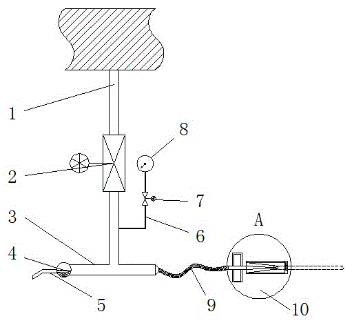
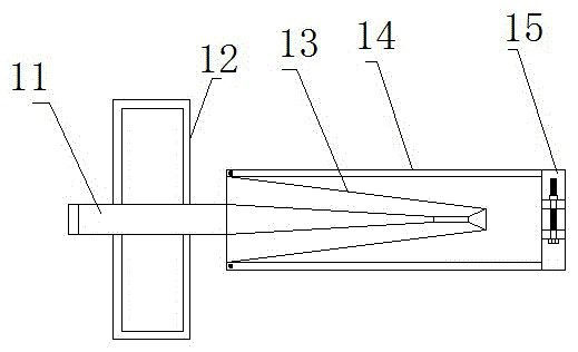
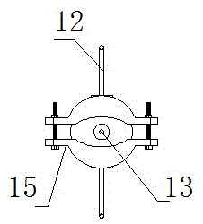
[0015] An oil pipe steam purging device of the present invention comprises a steam supply pipe 1, one end of the steam supply pipe 1 is connected with a steam source, and the other end is connected with a steam outlet pipe 3, and the middle part of the steam outlet pipe 3 is perpendicular to the steam supply pipe 1 One end of the steam outlet pipe 3 is provided with a drain pipe 5 with an automatic drain valve 4, and the other end is connected with a depressurization speed-up spray gun 10; Steam pipe 11, the rear end of the steam inlet pipe 11 is connected with the steam outlet pipe 3, and the front end is provided with a conical steam nozzle 13 that is thin before and thick at the rear. The cavity is conical with thin front and thick at the back, the cavity in the middle section is cylindrical, and the cavity in the front section is conical with thick front and thin ...


PUM


Abstract

The invention discloses an oil tube steam blowing device which comprises a steam supply tube. One end of the steam supply tube is connected with a steam source, and the other end of the steam supply tube is connected with a steam outlet tube. The middle of the steam outlet tube is perpendicularly connected with the steam supply tube. One end of the steam outlet tube is provided with a drainage tube with an automatic steam trap, and the other end of the steam outlet tube is connected with a depressurization and acceleration spraying gun. The depressurization and acceleration spraying gun comprises a sleeve and a steam inlet tube penetrating into the sleeve. The rear end of the steam inlet tube is connected with the steam outlet tube, and the front end of the steam inlet tube is provided with a conical steam nozzle. An oil tube clamp is arranged at the tail end of the sleeve. A steam isolation valve is arranged on the steam supply tube. The oil tube steam blowing device has the advantages that high-temperature and high-pressure steam can be depressurized and accelerated, more pressure of the steam can be converted into kinetic energy, and the steam is used for blowing the inner wall of an oil tube at high speed, so that sundries remaining on the inner wall of an oil tank, oxidation layers and other sundries can be effectively removed, the cleanliness inside the oil tube is ensured, guarantees are provided for safe and stable operation of the whole hydraulic control system, and personal safety of constructors is ensured.

Description

technical field [0001] The invention relates to an oil pipe steam purging device. Background technique [0002] With the continuous development and progress of science and technology, hydraulic oil control is more widely used in industrial production fields due to its precise control and convenient operation. However, the internal cleanliness of the pipeline of the hydraulic oil control system is quite high. The treatment method is not easy to remove the impurities attached to the inside of the pipeline. Using steam to purge the inside of the pipeline has become the first choice for cleaning the inside of the oil pipeline of the hydraulic control system. The conventional steam purge directly leads a thin tube from the steam pipeline and inserts it into the oil pipeline. Due to the high temperature and high pressure of the steam, the construction personnel are more likely to be scalded or injured by the reaction force of the steam pressure, making steam blowing the oil pipe a...

Claims


Application Information

Patent Timeline
Patent Type & Authority Patents(China)
IPC IPC(8): B08B9/032
CPCB08B9/0327
Inventor 兰京成李登生赵坤解富武
Owner POWERCHINA SEPCO1 ELECTRIC POWER CONSTR CO LTD
Features
  • R&D
  • Intellectual Property
  • Life Sciences
  • Materials
  • Tech Scout
  • Unparalleled Data Quality
  • Higher Quality Content
  • 60% Fewer Hallucinations
Learn More