

Vehicle immobilizer method and system
A vehicle, non-parking technology, applied in the field of stopping the vehicle and the system, to prevent the transmission from overheating
- Summary
- Abstract
- Description
- Claims
- Application Information
AI Technical Summary
Problems solved by technology
Method used
Image

Examples
Embodiment Construction
[0027] As required, detailed embodiments of the present disclosure are disclosed herein; however, it should be understood that the disclosed embodiments are merely examples that may be embodied in various and alternative forms. The figures are not necessarily to scale; some features may be exaggerated or minimized to show details of particular components. Therefore, specific structural and functional details disclosed herein are not to be interpreted as limiting, but merely as a representative basis for teaching one skilled in the art to variously employ the claimed subject matter.
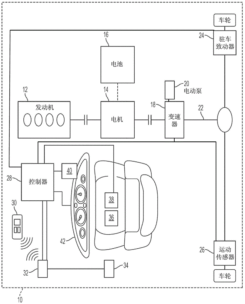
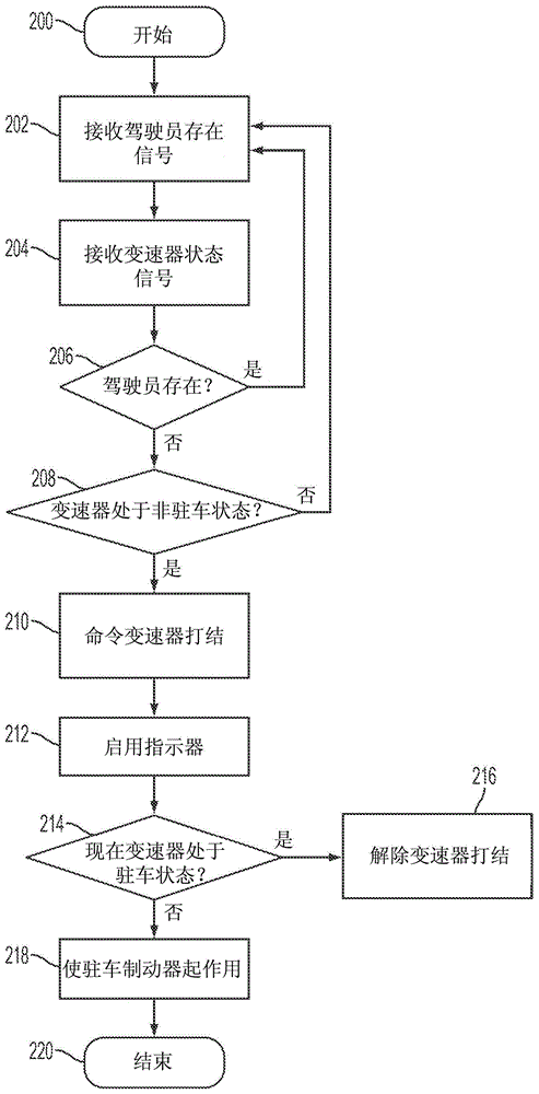
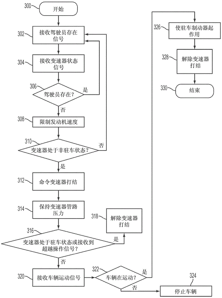
[0028] A distracted driver may leave the vehicle without first placing the transmission in Park and stopping the vehicle without operating the automatic transmission. Drivers of hybrid electric vehicles with a start / stop feature that shuts off the engine when the vehicle comes to a stop and in other situations frequently experience situations in which the driver may stop the vehicle without proper...
PUM
 Abstract
Description
Claims
Application Information