Initiating explosive drying device

A technology for drying device and priming charge, which is applied to explosives, explosives processing equipment, offensive equipment, etc., can solve the problems of long drying time of vacuum dryer, low drying quality of priming charge, and low production process efficiency, and achieves the drying level. Fully qualified, shortened drying time, high production efficiency

Active Publication Date: 2014-09-17
HUNAN NANLING IND EXPLOSIVE MATERIAL CO LTD
View PDF2 Cites 0 Cited by
  • Summary
  • Abstract
  • Description
  • Claims
  • Application Information

AI Technical Summary

Problems solved by technology

This kind method has following shortcoming: (1) in this process, need to manually put the medicine dish that priming charge is housed into vacuum desiccator one by one, workload is big, consumes manpower and time; (2) because priming charge has high Sensitivity, friction and static electricity may cause it to explode, so there is a great potential safety hazard in the manual operation process; (3) The drying time of the vacuum dryer is too long, which reduces the efficiency of the entire production process; and the vacuum dryer is under pressure The container has high requirements on the sealing effect of the dryer, and the equipment is huge. It is difficult to meet the requirements in actual use, so that the drying quality of the primer is not high.

Method used


Image

  • Initiating explosive drying device
  • Initiating explosive drying device

Examples


Embodiment 1

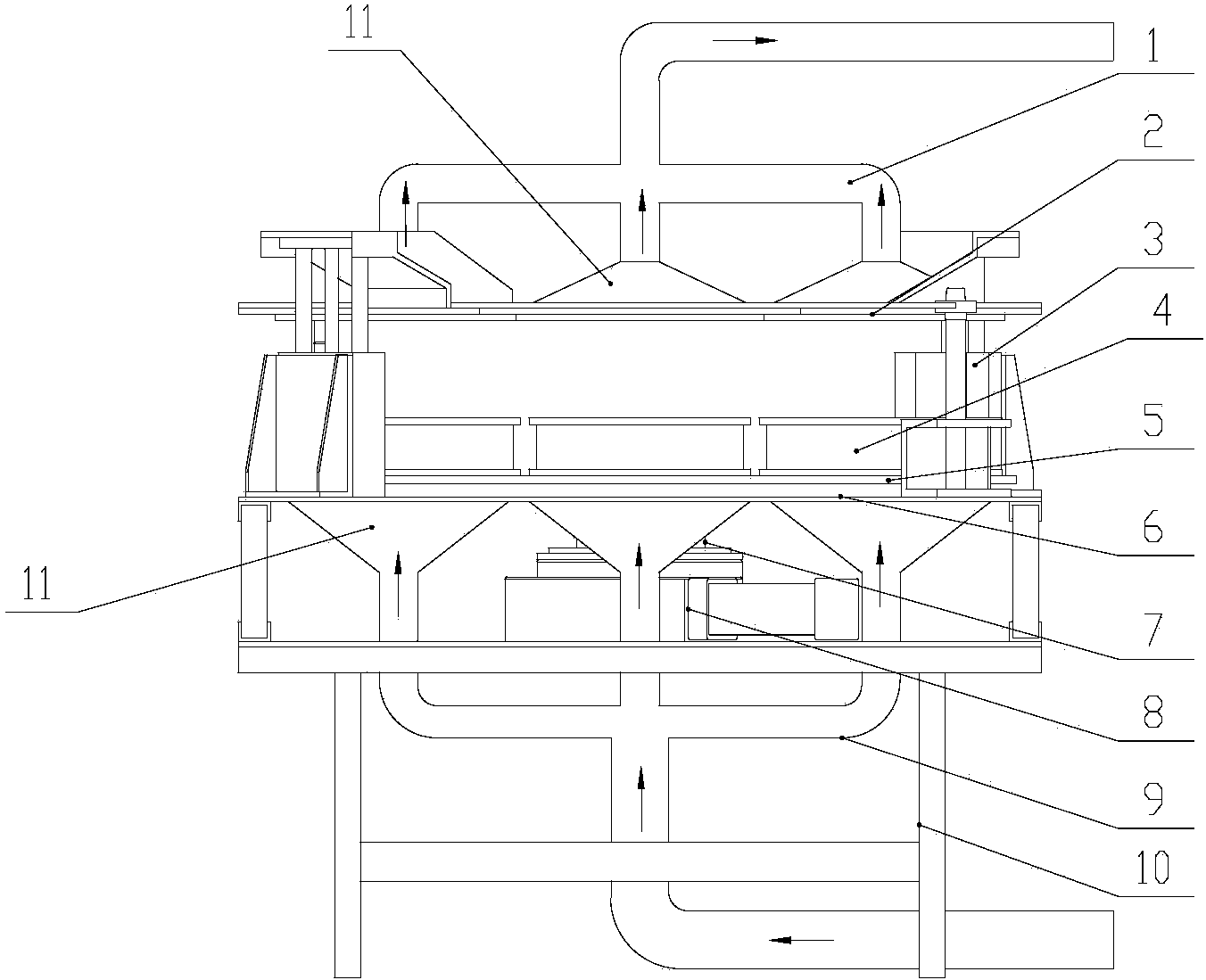
[0033] A kind of priming powder drying device, see figure 1 , including the first pipeline 1, the upper wind hood fixing plate 2, the first cylinder 3, the medicine box 4, the medicine box tray 5, the lower wind hood fixing plate 6, the second air cylinder 7, the second pipeline 9, the base 10 and the controller , wherein the second pipeline 9 is a hot air inlet pipeline, and the first pipeline 1 is an air outlet pipeline.

[0034] The medicine box tray 5 is arranged on the base 10 through the rotary indexing cylinder 8, the medicine box tray 5 is arranged on the top of the rotary indexing cylinder 8, and N medicine boxes 4 are arranged on the medicine box tray 5 , N is greater than or equal to 2, preferably the medicine box 4 is evenly distributed on the medicine box tray 5 along the circumference, N is 4-12, and the medicine box tray realizes the indexing rotation with the rotation of the rotary indexing cylinder, which is convenient for the manipulator to move from the medi...

Embodiment 2

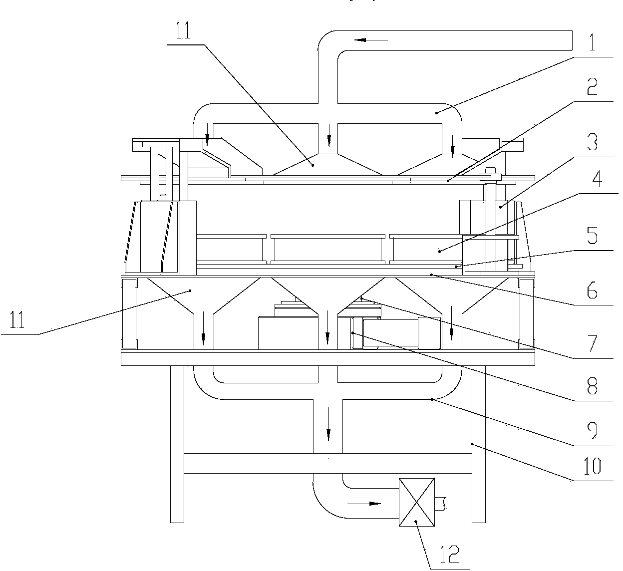
[0046] The difference between this embodiment and Embodiment 1 is that the second pipeline 9 is an air outlet pipeline connected to the vacuum pump 12, and the first pipeline 1 is a hot air inlet pipeline. For details, see figure 2 , which works as follows:

[0047] Before drying, the second cylinder 7 controls the lower hood fixed plate 6 to be at the lowest position, and the first cylinder 3 controls the upper hood fixed plate 2 to be at the uppermost position; the rotary indexing cylinder 8 drives the medicine box tray to rotate at 5 degrees, and the In the previous process, the medicine boxes 4 with wet primers are placed on the medicine box tray 5 in sequence. When the medicine box tray 5 is filled with medicine boxes 4, the first cylinder 3 controls the upper windshield fixing plate 2 to move vertically downward. , the second cylinder 7 controls the lower windshield fixed plate 6 to move vertically upwards until the air holes on the upper windshield fixed plate 2 are fu...


PUM


Abstract

The invention provides an drying device drying device, comprising a first pipeline, an upper fan housing fixing plate, a first cylinder, drug boxes, a drug box pallet, a lower fan housing fixing plate, a second cylinder, a second pipeline and a controller. The drug box tray is arranged on a base, and is provided with a plurality of drug boxes; the lower fan housing fixing plate is arranged on the top of the second cylinder and is located below the in the drug box pallet; the upper fan housing fixing plate is arranged on the top of the first cylinder and located right above the drug box pallet; the upper fan housing fixing plate and the lower fan housing fixing plate are provided with air holes; the first pipeline and the upper fan housing fixing plate, and the second pipeline and the lower fan housing fixing plate are in a flexible connection mode; the air holes on the upper fan housing fixing plate are communicated with the inside of the first pipe, and the air holes on the lower fan housing fixing plate are communicated with the inside of the second pipeline; and the first cylinder and the second cylinder are all connected with the controller. The invention adopts automatic production, avoids direct artificial contact with the explosive, greatly shortens the drying time and improves production efficiency.

Description

technical field [0001] The invention relates to the field of drying devices, in particular to a drying device for primary explosives. Background technique [0002] The drying of priming powder is an important process in the production of priming powder. The traditional drying method is to use vacuum drying method. The specific operation steps are as follows: manually put the medicine tray containing wet priming powder into the vacuum dryer, and seal the vacuum dryer. Get up, and then pass hot water or water vapor into the jacket of the vacuum dryer to heat the dryer, and at the same time, vacuum the dryer through a vacuum pump to complete vacuum drying. This kind method has following shortcoming: (1) in this process, need to manually put the medicine dish that priming charge is housed into vacuum desiccator one by one, workload is big, consumes manpower and time; (2) because priming charge has high Sensitivity, friction and static electricity may cause it to explode, so the...

Claims


Application Information

Patent Timeline
Patent Type & Authority Applications(China)
IPC IPC(8): C06B21/00
Inventor 刘宇星奉朝晖王凯孙建仪郝静达刘亚东陈太林郑磊吕忠易建伟王春华黄锦鸿孙磊李海雄肖启明江海
Owner HUNAN NANLING IND EXPLOSIVE MATERIAL CO LTD
Why Eureka
Try Eureka