Underground remote control locking device and remote control locking method

A technology of remote control lock and lock body, which is applied in natural gas drilling and petroleum fields, and can solve problems such as cumbersome operation, intermittent pins, and complex downhole working conditions

Active Publication Date: 2014-09-17
BC P INC CHINA NAT PETROLEUM CORP +1
View PDF8 Cites 2 Cited by
  • Summary
  • Abstract
  • Description
  • Claims
  • Application Information

AI Technical Summary

Problems solved by technology

At present, the locking mechanisms used in most tools have the following deficiencies: some mechanisms cannot operate the locking and releasing of the locking mechanism in the tool through ground remote control, which is not conducive to the control of the tool; some mechanisms fix the two parts through pins , when separation is required, increase the pressure difference by throwing a ball and shear the pin to achieve separation. This mechanism can only be used to release the locking mechanism once and cannot be reused. It is not suitable for tools that need to be controlled multiple times in the well. The downhole working condi

Method used


Image

  • Underground remote control locking device and remote control locking method
  • Underground remote control locking device and remote control locking method

Examples


Embodiment 1

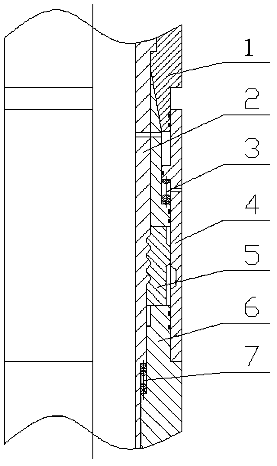
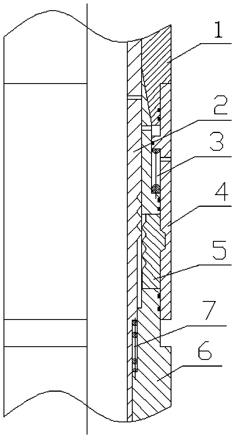
[0016] Embodiment 1: as figure 1 , figure 2 as shown,

[0017] The downhole remote control locking device consists of an upper housing 1, a locked body 2, an unlocking sleeve spring 3, an unlocking sleeve 4, a lock block 5, a body 6, and a locked body spring 7. There are bypass holes on the main body 6, the locked body 2 and the unlocking sleeve 4. The locked body 2 is installed on the inner side of the main body 6, the unlocking sleeve 4 is installed on the outer side of the main body 6, and the main body 6 and the upper casing 1 are connected with threads. The middle part of the body 6 is slotted, and the lock block 5 is installed in the groove of the body 6, and there are at least two slots between the lock block 5 and the body 6 in the circumferential direction. There is a groove in the middle of the locked body 2, and the tooth shape of the axial section meshes with the lock block 5. If the number of axial teeth is large, the axial thrust distributed on each tooth is ...

Embodiment 2

[0021] Embodiment 2: as figure 1 , figure 2 as shown,

[0022] Place the locked body spring and the unlocking sleeve spring on the middle part of the body and the lower step surface respectively, install the lock block in the through hole of the body, install the unlocking sleeve outside the body, connect the upper shell and the body with threads, and finally Put the locked body into the body from top to bottom.

[0023] During normal drilling, the mechanism is in the release state. When locking is required, increase the working displacement to the control displacement. The locked body is aligned with the bypass hole of the body, and the unlocking sleeve moves downward under the action of the pressure difference between the inner and outer rings. , the lock block is engaged with the annular groove of the locked body. At this time, it returns to the normal working displacement, and the mechanism is still in the locked state.

[0024] When release is required, the pump is s...


PUM


Abstract

The invention relates to an underground remote control locking device and a remote control locking method, and belongs to the technical field of petroleum and natural gas well drilling. By-pass holes are formed in a body, a locked body and an unlocking sleeve; the locked body is arranged at the inner side of the body, the unlocking sleeve is arranged at the outer side of the body, and the body is connected with an upper casing through screw threads; the middle part of the body is provided with grooves, locking blocks are arranged in the grooves of the body, and the number of the locking blocks and the grooves of the body in the circumferential direction is at least two; the middle part of the locked body is provided with a concave groove, and the axial profile is in a tooth shape and is engaged with the locking blocks; the inner side of the lower part of the unlocking sleeve is provided with an annular concave groove, and the annular concave groove is matched with an inclined surface lug boss of the locking blocks; an unlocking sleeve spring is arranged in an annular space formed between the unlocking sleeve and the upper end surface of the intermediate-diameter part of the body, and a locked body spring is arranged in an annular space formed between the lower part of the locked body and the side surface of the major-diameter end of the body; a sealing ring is arranged in a corresponding position of the unlocking sleeve and the body. The underground remote control locking device and the remote control locking method have the advantage that the multiple locking and unlocking of components is realized.

Description

technical field [0001] The invention relates to an underground remote control locking device and a remote control locking method. It belongs to the technical field of oil and natural gas drilling. Background technique [0002] In the design of downhole tools for oil drilling, many situations involve the locking and releasing functions of a certain part of the tool. At present, the locking mechanisms used in most tools have the following deficiencies: some mechanisms cannot operate the locking and releasing of the locking mechanism in the tool through ground remote control, which is not conducive to the control of the tool; some mechanisms fix the two parts through pins , when separation is required, increase the pressure difference by throwing a ball and shear the pin to achieve separation. This mechanism can only be used to release the locking mechanism once and cannot be reused. It is not suitable for tools that need to be controlled multiple times in the well. The downh...

Claims


Application Information

Patent Timeline
IPC IPC(8): E21B23/00
Inventor 林雅玲崔凯徐丙贵郭慧娟王雪
Owner BC P INC CHINA NAT PETROLEUM CORP
Why Eureka
Try Eureka