Laser ignition device of single fiber structure

A laser ignition, single-fiber technology, used in weapon accessories, fuzes, offensive equipment, etc., can solve the complex process, difficult engineering, and consistent reflectivity of the optical window of the laser detonator at the interface between the dual-fiber optical cable and the laser detonator. Advanced problems, to achieve quantitative detection of optical path continuity, simple connection method, and good consistency

Inactive Publication Date: 2014-09-17
CHANGCHUN INST OF OPTICS FINE MECHANICS & PHYSICS CHINESE ACAD OF SCI
View PDF6 Cites 6 Cited by
  • Summary
  • Abstract
  • Description
  • Claims
  • Application Information

AI Technical Summary

Problems solved by technology

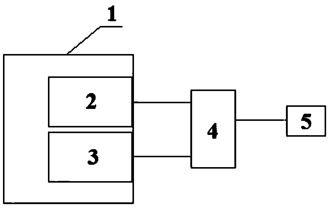
[0005] (1) The target application system generally requires the detonator to complete multiple actions, and the number of laser detonators may reach dozens or even hundreds. If this dual-fiber structure is adopted, the number of optical fibers and optical fiber connectors is huge, which increases the system cost. The complexity of wiring and installation;
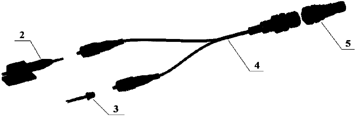
[0006] (2) The process at the interface between the dual-fiber optical cable and the laser detonator is complicated, not only requiring the two optical fibers in the dual-fiber optical cable 4 to be coaxially symmetrical, but also requiring that the reflectivity of the light window of the laser detonator 5 be high in consistency. The engineering of the process is very difficult

Method used


Image

  • Laser ignition device of single fiber structure
  • Laser ignition device of single fiber structure
  • Laser ignition device of single fiber structure

Examples


Embodiment Construction

[0014] The present invention will be described in further detail below in conjunction with the accompanying drawings and embodiments.

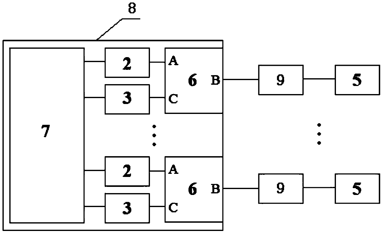
[0015] Such as image 3 As shown, a laser ignition device with a single-fiber structure includes: a novel ignition controller 8, a single-fiber cable 9 and a laser detonator 5. The novel ignition controller 8 is connected with the laser detonator 5 through a single optical fiber cable 9 . The new ignition controller 8 includes laser 2, detector 3, fiber optic circulator 6, and drive controller 7. The A end and the incident end are connected to the laser 2 , and the C end and the output end of the optical fiber circulator 6 are connected to the detector 3 . The laser 2 and the detector 3 are respectively connected to the drive control circuit 7 .

[0016] When the invention works, two functions of ignition and optical path continuity detection can be completed. When the device is ignited, the drive controller 7 injects an ignition current i...


PUM


Abstract

The invention discloses a laser ignition device of a single fiber structure and relates to the technical field of semi-conductor lasers. The laser ignition device comprises a novel ignition controller and a laser detonator which are connected through a single fiber optical cable, wherein the novel ignition controller comprises at least one group of a laser and a detector which are separately connected with an optical fiber circulator; each laser is connected with the incidence end of the corresponding optical fiber circulator; each detector is connected with the exit end of the corresponding optical fiber circulator; the single fiber optical cable is connected with the incidence and exit ends of the optical fiber circulators; the novel ignition controller also comprises a driving controller which is connected with all the lasers and detectors. The single fiber optical cable is used for connecting the laser ignition device of the single fiber structure, the number of optical cables is reduced by half and the installation and the wiring of a multi-path ignition system are facilitated; a connection method is simple; the transmissivity and reflectivity of an optical membrane can be accurately controlled; the consistency of various paths of reflection light is relatively good during light path continuity measurement and the quantitative measurement on the light path continuity is facilitated.

Description

technical field [0001] The invention relates to the technical field of semiconductor laser applications, in particular to a semiconductor laser ignition device based on a single optical fiber structure. Background technique [0002] There is no electric initiating element in the laser ignition device, and the explosives, pyrotechnics and power supply are truly isolated, and the anti-electromagnetic interference characteristics of the optical fiber eliminate the parasitic signals in the laser ignition device. Compared with the design mode, the danger of accidental ignition of the laser ignition device in electromagnetic environments such as static electricity and radio frequency will be completely overcome, and the safety will be fundamentally improved. As a new type of ignition technology, laser ignition has been paid more and more attention by various countries, and the development of practical laser ignition system is very rapid. [0003] The laser ignition device require...

Claims


Application Information

Patent Timeline
Patent Type & Authority Applications(China)
IPC IPC(8): F42C19/00
Inventor 曹军胜彭航宇王彪高志坚尹红贺宁永强
Owner CHANGCHUN INST OF OPTICS FINE MECHANICS & PHYSICS CHINESE ACAD OF SCI
Why Eureka
Try Eureka