
A subsurface defect detection device and detection method based on AC electromagnetic field

A technology of subsurface defects and alternating electromagnetic fields, applied in the direction of material magnetic variables, etc., can solve problems such as restricting development, failing to meet the comprehensive detection requirements of deep defects in equipment structures, and unable to realize the detection of non-surface defects in workpieces, so as to improve intrinsic safety Level, realize the effect of intelligent identification and quantification

Inactive Publication Date: 2016-02-24
CHINA UNIV OF PETROLEUM (EAST CHINA)
View PDF5 Cites 0 Cited by
  • Summary
  • Abstract
  • Description
  • Claims
  • Application Information

AI Technical Summary

Problems solved by technology

However, since most of the current ACFM technology theory is excited by a single-frequency sinusoidal alternating current signal of about 6000 Hz, due to the skin effect, the induced current is concentrated on the surface of the workpiece, and the penetration depth of the induced electromagnetic field is relatively shallow, so it is impossible to realize the detection of non-surface defects in the workpiece. Detection is generally only applicable to the detection of surface defects, so that the existing ACFM technology and equipment cannot meet the comprehensive detection requirements of different types of deep defects in equipment structures, which greatly reduces the practicability and detection efficiency of AC electromagnetic field detection technology. To a certain extent, the development and deepening of this technology are limited. How to improve the detection sensitivity of ACFM detection technology for hidden defects in the subsurface and deep layers of structures is very important.

Method used


Image

  • A subsurface defect detection device and detection method based on AC electromagnetic field

Examples


Embodiment Construction

[0018] The present invention will be further described below in conjunction with accompanying drawing:

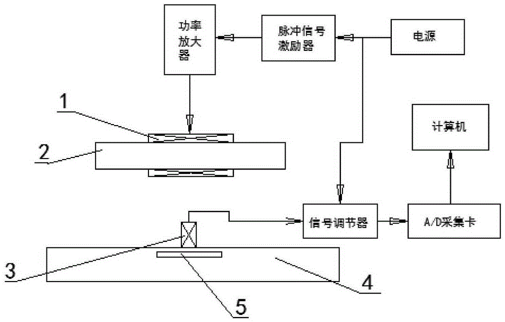
[0019] Such as figure 1 Shown: a subsurface defect detection device based on AC electromagnetic field, including excitation coil 1, magnetic core 2, detection coil 3, signal conditioner, A / D acquisition card, computer, power supply, pulse signal exciter and power amplifier, The detection coil 3 is located below the middle of the magnetic core 2 and is close to the workpiece defect 5 of the workpiece 4. The signal output terminal of the detection coil 3 is connected to the computer through the signal conditioner and the A / D acquisition card in turn, and the power supply is simultaneously connected with the signal conditioner and the pulse. The signal exciter is connected. The signal output end of the pulse signal exciter is connected to the excitation coil 1 through the power amplifier. The excitation coil 1 is located in the middle of the magnetic core 2. The signal conditi...


PUM


Abstract

The invention discloses a subsurface defect detection device and method based on an alternative current electromagnetic field. The subsurface defect detection device comprises an excitation coil, a magnetic core, a detection coil, a signal adjuster, an A / D (Analog-to-Digital) acquisition card, a computer, a power supply, a pulse signal exciter and a power amplifier. Compared with the prior art, the subsurface defect detection device generates a periodic pulse signal through a pulse signal generator, the periodic pulse signal is applied to an excitation probe, then an alternating pulse magnetic field is sensed on the subsurface and the deep layer of a workpiece, filtering and denoising are continued by a signal modulation circuit, the data acquisition card based on a USB (Universal Serial Bus) is adopted for acquisition, an instantaneous signal analysis method is adopted to draw sensation voltage signal peak value waveforms in the BX direction and the BZ direction, and thus intelligent recognition and quantification on subsurface defects and deep layer defects are achieved. By virtue of the subsurface defect detection device and method, the defects of a deep layer defect alternative current electromagnetic field detection technique are effectively made up, and a completely novel method is provided for high-sensitivity comprehensive rapid quantitative recognition on subsurface detects and deep layer detects of a structural body, and the essential safety level of a facility structure is improved.

Description

technical field [0001] The invention relates to an electromagnetic non-destructive testing method, in particular to a sub-surface defect testing device and testing method based on an AC electromagnetic field. Background technique [0002] AC electromagnetic field detection (ACFM) is a non-contact electromagnetic non-destructive testing technology. Due to its unique advantages such as non-contact detection, clear mathematical model, high quantitative recognition accuracy, fast detection speed, and insensitivity to the lift-off movement of the probe, it has been widely used. Used in civil engineering, petrochemical, electric power and nuclear industries and other fields. However, since most of the current ACFM technology theory is excited by a single-frequency sinusoidal alternating current signal of about 6000 Hz, due to the skin effect, the induced current is concentrated on the surface of the workpiece, and the penetration depth of the induced electromagnetic field is relat...

Claims


Application Information

Patent Timeline
Patent Type & Authority Patents(China)
IPC IPC(8): G01N27/82
Inventor 李伟陈国明张传荣刘涛
Owner CHINA UNIV OF PETROLEUM (EAST CHINA)
Learn More