Photoelectric key door lock device

A door lock and key technology, applied in the field of photoelectric key door lock device, can solve the problems such as the inconvenience of opening the door with the key, and achieve the effect of solving the inconvenience of opening the door

Active Publication Date: 2014-09-17
INST OF SEMICONDUCTORS - CHINESE ACAD OF SCI
View PDF6 Cites 11 Cited by
  • Summary
  • Abstract
  • Description
  • Claims
  • Application Information

AI Technical Summary

Problems solved by technology

[0004] In view of this, the main purpose of the present invention is to provide a photoelectric key door lock device to overcome the defect that the door lock batter

Method used


Image

  • Photoelectric key door lock device

Examples


Embodiment Construction

[0022] In order to make the object, technical solution and advantages of the present invention clearer, the present invention will be described in further detail below in conjunction with specific embodiments and with reference to the accompanying drawings.

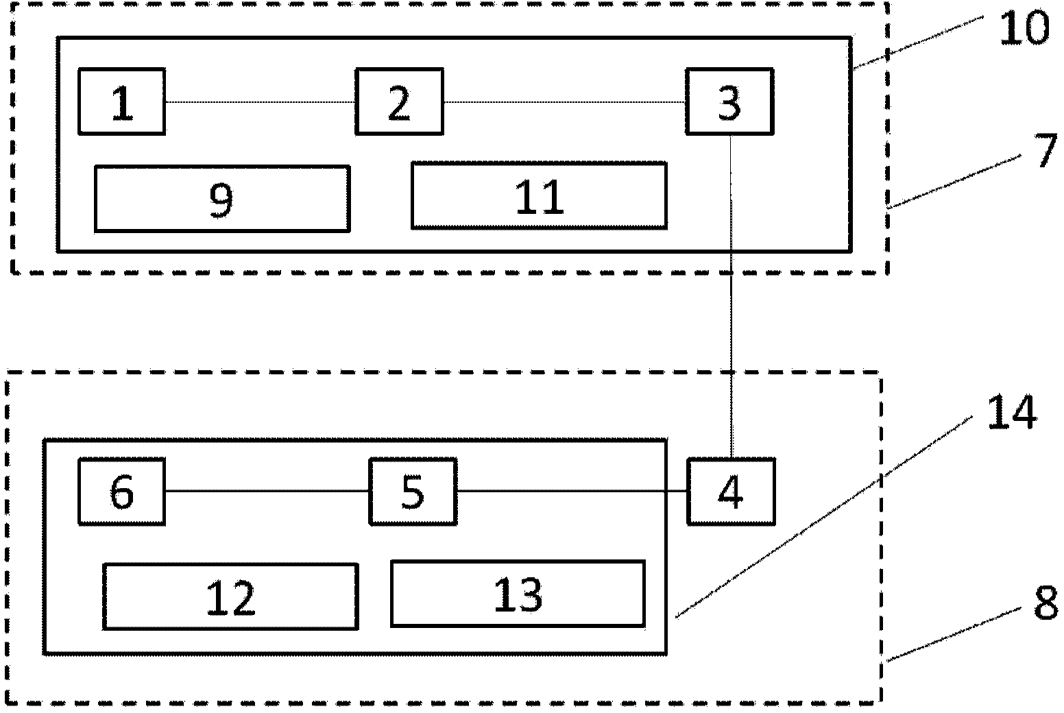
[0023] Such as figure 1 as shown, figure 1 It is a schematic diagram of a photoelectric key door lock device according to an embodiment of the present invention. The photoelectric key door lock device includes a light-emitting key 7 and a photoelectric door lock 8, wherein the light-emitting key 7 sends out an optical signal containing a key, and the photoelectric door lock 8 receives the light signal After the light signal is decoded, the key contained in the light signal is matched with the key stored in itself. If the match is successful, the door lock is opened.

[0024] Wherein, the light-emitting key 7 includes a first single-chip microcomputer 1, a light-emitting diode driver chip 2 and a light-emitting diode 3 co...


PUM


Abstract

The invention discloses a photoelectric key door lock device which comprises a luminous key and a photoelectric door lock, wherein the luminous key emits a light signal containing a private key; the photoelectric door lock receives the light signal, decodes the private key contained in the light signal, and matches the private key with a private key stored in the photoelectric door lock; the door lock is opened under a condition of successful matching. Due to the photoelectric key door lock device, the shortcoming that a door lock battery is required to be replaced when a door is opened through a radio frequency card is overcome; the problem that the door is inconveniently opened by the key under a condition of no light at night is solved.

Description

technical field [0001] The invention relates to the technical field of anti-theft door locks, in particular to a photoelectric key door lock device based on visible light lighting communication. Background technique [0002] At present, most household door locks use keys, and hotel door locks mostly use the method of swiping radio frequency cards to open the door. It is inconvenient to open the door with a key when there is no lighting at night; the way to open the door with a radio frequency card is convenient for hotel management, but because the door needs to continuously transmit radio frequency signals, it is in a standby state at any time, and it needs to consume power continuously. The battery in the door lock needs to be replaced in less than 2 years, causing inconvenience to hotel maintenance. Contents of the invention [0003] (1) Technical problems to be solved [0004] In view of this, the main purpose of the present invention is to provide a photoelectric ke...

Claims


Application Information

Patent Timeline
IPC IPC(8): G07C9/00
Inventor 陈伟刘建国祝宁华
Owner INST OF SEMICONDUCTORS - CHINESE ACAD OF SCI
Why Eureka
Try Eureka