Multi-phase grid driver and display panel thereof

A display panel and driver technology, which is applied in the direction of instruments, static memory, static indicators, etc., can solve the problems of increasing the number of wires and increasing the frame width of the display panel, and achieve the effect of reducing the number of wires

Active Publication Date: 2014-09-17
AU OPTRONICS CORP
View PDF5 Cites 8 Cited by
  • Summary
  • Abstract
  • Description
  • Claims
  • Application Information

AI Technical Summary

Problems solved by technology

[0004] However, as the resolution of the display panel continues to increase, the number of control signals required to be provided to the gate driver by the timing controller in the liquid crystal display screen also

Method used


Image

  • Multi-phase grid driver and display panel thereof
  • Multi-phase grid driver and display panel thereof
  • Multi-phase grid driver and display panel thereof

Examples


Embodiment Construction

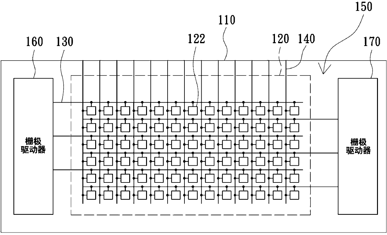
[0030] figure 1 is a schematic diagram of a display panel 100 according to an embodiment of the present invention. Please refer to figure 1 In this example, the multi-phase gate driver 160 and the multi-phase gate driver 170 are produced by using a multi-phase array substrate gate driving technology. exist figure 1 Among them, the substrate 110 includes a pixel matrix 120 composed of a plurality of pixels 122 . Each pixel 122 is electrically coupled to a corresponding gate line 130 and a corresponding source line 140 . And as figure 1 As shown, the multi-phase gate drivers 160 and 170 are directly fabricated in the peripheral area 150 of the display panel 100 formed by the substrate 110 , and are disposed on opposite sides of the display panel 100 . In this embodiment, taking double-sided gate driver driving as an example, the multi-phase gate driver 160 is electrically coupled to the odd-numbered gate lines 130, while the multi-phase gate driver 170 is electrically coupl...


PUM


Abstract

A multi-phase grid driver is arranged on the periphery of a display panel and comprises a start-stop signal generating circuit and a plurality of shift register modules. The start-stop signal generating circuit sequentially outputs a plurality of start-stop signals on the basis of a first control signal and a plurality of groups of clock signals. Each shift register module comprises a plurality of shift register units. The Mth shift register unit of one of the shift register modules outputs a corresponding grid signal on the basis of the Mth group of clock signals, the Mth start signal and a grid signal of the Mth shift register unit of the next-level shift register module, wherein M is an integer.

Description

technical field [0001] The present invention relates to a gate driver, in particular to a set of multi-phase gate drivers. Background technique [0002] Liquid crystal display screens have the advantages of high image quality, small size and light weight, so they are widely used in consumer electronics products such as smartphones, notebook computers, desktop monitors and televisions, and have replaced traditional cathode ray tube display screens. It has become the mainstream of display screens. [0003] The current liquid crystal display screen mainly uses multi-phase array substrate gate drive (Multi-phase Gate Driven Array) technology to directly manufacture the gate driver in the peripheral area of ​​the display panel formed by the array substrate, so as to use these gate drivers to drive High resolution display panel. [0004] However, as the resolution of the display panel continues to increase, the number of control signals required to be provided to the gate driver...

Claims


Application Information

Patent Timeline
IPC IPC(8): G09G3/36G11C19/28
CPCG11C19/287G09G3/3648G09G3/3666G09G3/3677G09G2300/0426G09G2310/0286G09G2310/08G11C19/00
Inventor 柯健专蔡孟杰
Owner AU OPTRONICS CORP
Why Eureka
Try Eureka