A main power station for an offshore gas field platform and its application method

A technology for main power stations and gas fields, which is applied in the field of main power stations, can solve the problems of low energy utilization rate of gas turbine generator sets, low thermal efficiency of gas turbine generator sets, high investment fuel operating costs, etc., so as to improve the flexibility of fuel utilization and daily The effect of small maintenance workload and convenient on-site operation and management

Active Publication Date: 2016-03-16
CHINA NAT OFFSHORE OIL CORP +1
View PDF6 Cites 0 Cited by
  • Summary
  • Abstract
  • Description
  • Claims
  • Application Information

AI Technical Summary

Problems solved by technology

[0002] The traditional main power station on the offshore gas field platform uses a gas turbine generator set or a reciprocating dual-fuel generator set. When the load of the main power station on the offshore gas field platform is small, even lower than 2000-3000kW, the above two generator sets have investment and fuel costs. Defects such as high operating costs
For a gas turbine generator set, its thermal efficiency is low, that is, to generate electricity with the same power, the fuel consumed by a gas turbine generator set is far greater than that of a reciprocating dual-fuel generator set
In addition, limited by the specifications of the gas turbine generator set, the general ISO power is greater than 3500kW, so there is a long-term low-load operation condition of the gas turbine generator set, which makes the thermal efficiency of the gas turbine generator set lower, that is, the gas turbine generator set The energy efficiency of the flat generator set is low
For reciprocating dual-fuel generator sets, diesel ignition is required for their operation, so there are disadvantages such as high operating costs

Method used


Image

  • A main power station for an offshore gas field platform and its application method
  • A main power station for an offshore gas field platform and its application method

Examples


Embodiment Construction

[0014] The present invention will be described in detail below in conjunction with the accompanying drawings and embodiments. The present invention uses a diesel power generation system to connect several natural gas power generation systems in parallel. Since the connection and control methods of several natural gas power generation systems are the same, it will only be described in detail by taking a diesel power generation system in parallel with a natural gas power generation system as an example:

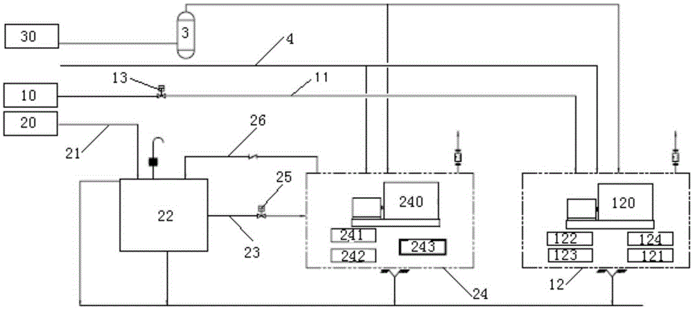
[0015] like figure 1 As shown, the present invention includes a natural gas power generation system and a diesel power generation system, wherein the natural gas power generation system includes a natural gas source 10, and the natural gas source 10 communicates with a reciprocating gas generator set 12 through a pipeline 11. A one-way valve 13 is provided. The reciprocating gas generating set 12 comprises a reciprocating gas generating set 120, a gas filter 121, a central coo...


PUM


Abstract

The invention relates to a main power plant for an offshore gas field platform and an application method of the main power plant. The main power plant comprises a plurality of natural gas power generation systems connected in parallel and a diesel oil power generation system connected with the natural gas power generation systems in parallel. Each natural gas power generation system comprises a natural gas source and a gas power generator set communicated with the natural gas source through a first pipeline. The diesel oil power generation system comprises a diesel oil source, a diesel oil daily tank communicated with the diesel oil source through a second pipeline and a diesel power generator set communicated with the diesel oil daily tank through a third pipeline. The output end of the diesel oil power generator set is provided with a fourth pipeline for conveying the residual diesel oil in the diesel oil power generator set back to the diesel oil daily tank. The main power plant further comprises a control system for controlling the diesel oil power generation system and the natural gas power generation systems or the natural gas power generation systems to operate in a controlled mode.

Description

technical field [0001] The invention relates to an electrical device for an offshore gas field platform, in particular to a main power station for an offshore gas field platform and a usage method thereof. Background technique [0002] The traditional main power station on the offshore gas field platform uses a gas turbine generator set or a reciprocating dual-fuel generator set. When the load of the main power station on the offshore gas field platform is small, even lower than 2000-3000kW, the above two generator sets have investment and fuel costs. Defects such as high operating costs. For a gas turbine generator set, its thermal efficiency is low, that is, to generate electricity with the same power, the fuel consumed by a gas turbine generator set is far greater than that of a reciprocating dual-fuel generator set. In addition, limited by the specifications of the gas turbine generator set, the general ISO power is greater than 3500kW, so there is a long-term low-load ...

Claims


Application Information

Patent Timeline
Patent Type & Authority Patents(China)
IPC IPC(8): H02J3/38H02J3/46
Inventor 杜佳张强王建丰袁燕黄喆刘聪李新仲陈荣旗邱里洪毅徐正海魏澈侯广信吴尧增王祺皓张琳安维峥刘国锋张丽娜赵雷
Owner CHINA NAT OFFSHORE OIL CORP
Why Eureka
Try Eureka