Ultrasound Transducer And Processing Methods Thereof

An ultrasonic transducer and transducer technology, applied in the field of ultrasonic transducers for medical imaging, can solve the problems of difficult manufacturing angle and high cost

Active Publication Date: 2014-09-17
ACIST MEDICAL SYST
View PDF5 Cites 5 Cited by
  • Summary
  • Abstract
  • Description
  • Claims
  • Application Information

AI Technical Summary

Problems solved by technology

These approaches can be costly and impractical from a manufacturing standpoint, especially for small, single-purpose, high-frequency ultrasound devices used in relatively high volumes (eg, intravascular ultrasound catheters)

Method used


Image

  • Ultrasound Transducer And Processing Methods Thereof
  • Ultrasound Transducer And Processing Methods Thereof
  • Ultrasound Transducer And Processing Methods Thereof

Examples


Embodiment Construction

[0039] The following detailed description is exemplary in nature and is in no way intended to limit the scope, applicability or configuration of the invention. Rather, the following description provides some practical illustrations for implementing some embodiments of the invention. Examples of construction, materials, dimensions, and manufacturing processes are provided for selected elements, and all other elements employ techniques well known to those of ordinary skill in the art of the invention. Those skilled in the art will recognize that there are many suitable alternatives to many of the above-identified examples.

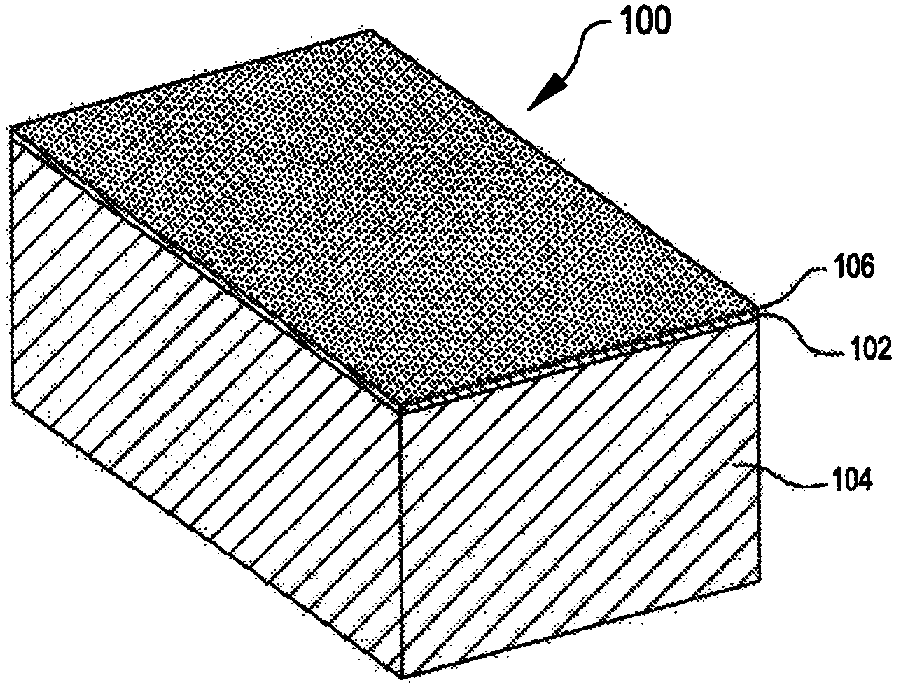
[0040] For example, certain examples of transducer stacks provided herein are applicable to intravascular ultrasound (IVUS) catheters having an ultrasound transducer placed within a catheter sheath. These examples are given for illustrative purposes only, and do not limit the application of the present invention to only IVUS catheters.

[0041] 1 illustrat...


PUM

PropertyMeasurementUnit
sizeaaaaaaaaaa
lengthaaaaaaaaaa
widthaaaaaaaaaa

Abstract

An ultrasonic transducer includes a backing element, an active element overlying the backing layer, and a matching element overlying the active element, the matching element having an inner surface that contacts the active element and an outer surface with a non-homogeneous texture and / or material composition. The matching element may be formed by subtractive or deposition techniques.

Description

[0001] priority [0002] This application claims priority to co-pending US Provisional Patent Application Serial No. 61 / 561,534, filed November 18, 2011, which is hereby incorporated by reference in its entirety. Background technique [0003] This application relates generally to ultrasound transducers. The present application further relates to ultrasound transducers for medical imaging. [0004] A trade-off in medical ultrasound imaging lies in penetration depth and spatial resolution. Higher ultrasound imaging frequencies enable higher spatial resolution at the expense of penetration depth. Lower ultrasound imaging frequencies enable deeper penetration at the expense of spatial resolution. It would be beneficial if a single ultrasound imaging device could image over a broad frequency range, operating at higher frequencies for better spatial resolution and lower frequencies for deeper penetration. [0005] Broadband ultrasound imaging devices may include the use of high ...

Claims


Application Information

Patent Timeline
Patent Type & Authority Applications(China)
IPC IPC(8): H04R17/00A61B8/00G01N29/24
CPCG01N29/24B06B1/06B06B1/067A61B8/00A61B8/12G01N29/2437G01N29/245G01N29/28G01N2291/02475
Inventor R·包蒂斯塔R·泽伦卡
Owner ACIST MEDICAL SYST
Why Eureka
Try Eureka