Clamping device for rear crossbeam of rear sub-frame

A technology of clamping device and rear subframe, applied in auxiliary devices, auxiliary welding equipment, welding/cutting auxiliary equipment, etc. Welding position accuracy, resistance to welding deformation, reducing the effect of space layout

Active Publication Date: 2016-06-01
GREAT WALL MOTOR CO LTD
View PDF10 Cites 0 Cited by
  • Summary
  • Abstract
  • Description
  • Claims
  • Application Information

AI Technical Summary

Problems solved by technology

The existing rear sub-frame rear beam welding device clamps the inner and outer plates of the rear sub-frame rear beam through cylinders and linear guide rails. The device does not have a positioning function and cannot control welding deformation, resulting in unstable welding dimensions; the large mechanism is not conducive to welding posture Optimization; because it is designed for manual welding, some welds cannot be completed at one time due to structural design defects of the tooling, and need to be completed by repair welding. This welding tooling and welding method cannot meet the requirements of high-efficiency production

Method used


Image

  • Clamping device for rear crossbeam of rear sub-frame
  • Clamping device for rear crossbeam of rear sub-frame
  • Clamping device for rear crossbeam of rear sub-frame

Examples


Embodiment Construction

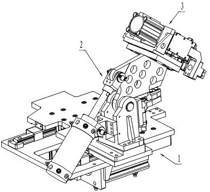
[0026] see figure 1 , The clamping device of the present invention is composed of a slide mechanism 1 , an indexing mechanism 2 and a clamping mechanism 3 . The sliding table mechanism 1 is the basic mechanism of the device, and the sliding table mechanism drives the indexing mechanism and the clamping mechanism to do linear motion, close to the rear sub-frame rear beam workpiece on the base or away from the workpiece. The indexing mechanism 2 is used to drive the clamping mechanism to swing into or out of the inner and outer plates of the rear crossbeam of the rear sub-frame. The clamping mechanism is used for clamping or loosening the inner and outer plates of the rear crossbeam workpiece of the rear subframe.

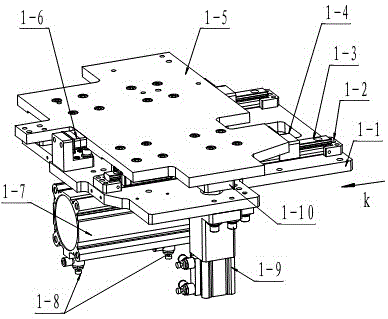
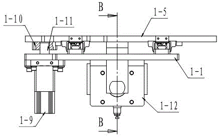
[0027] see figure 2 , image 3 , Figure 4 , the sliding table mechanism includes a sliding table mounting plate 1-1 and a sliding table 1-5, and the sliding table mounting plate fixes the sliding table cylinder 1-7. The sliding table cylinder 1-7 arranged hori...


PUM


Abstract

A clamping device for a rear cross beam of a rear subframe is composed of a sliding table mechanism, an inversion mechanism and a clamping mechanism, wherein the sliding table mechanism is provided with a sliding table positioning cylinder and a sliding table cylinder; a sliding table is driven by the sliding table cylinder to do linear motion to reach a working position or leave the working position; the sliding table positioning cylinder is used for fixing the sliding table on the working position; the inversion mechanism is positioned on the sliding table and is provided with an inversion cylinder; the inversion cylinder drives a clamping mechanism mounting plate to swing through an inversion connection plate, so that the clamping mechanism mounting plate and the clamping mechanism fixed with the clamping mechanism mounting plate are inversed to the rear cross beam of the rear subframe or inversed in an opposite direction to leave the rear cross beam of the rear subframe; the clamping mechanism is provided with a clamping cylinder; the clamping cylinder drives a clamping connecting rod assembly to move to clamp or loosen a workpiece. The clamping device for the rear cross beam of the rear subframe is compact in structure, the space layout is reduced, the influence of welding deformation can effectively resisted, the stability of welding quality is guaranteed, all weld joints can be exposed after the positioning and clamping of a tool, and one hundred percent accessibility of automatic welding by a robot can be realized.

Description

technical field [0001] The invention relates to a mechanical clamping device, in particular to a clamping device used for welding the rear beam of the rear sub-frame of an automobile. Background technique [0002] The rear cross member of the rear sub-frame is an important part of the rear sub-frame of the car, and it is also an important position for the installation of the swing arm. In addition to controlling the welding size and welding quality, it is also necessary to control the installation size of the swing arm during processing. The existing rear sub-frame rear beam welding device clamps the inner and outer panels of the rear sub-frame rear beam through the cylinder and linear guide rails. The device does not have a positioning function and cannot control welding deformation, resulting in unstable welding dimensions; the large mechanism is not conducive to welding posture Optimization; because it is designed for manual welding, some welds cannot be completed at one ...

Claims


Application Information

Patent Timeline
Patent Type & Authority Patents(China)
IPC IPC(8): B23K37/04
CPCB23K37/0435B23K37/0443
Inventor 苏春峰刘娜玲
Owner GREAT WALL MOTOR CO LTD
Why Eureka
Try Eureka