Assembling type movable cable holder for laying medium/high-voltage cable line in long-distance channel

A high-voltage cable, long-distance technology, used in pipeline supports, mechanical equipment, pipes/pipe joints/fittings, etc., can solve the problems of poor corrosion resistance, poor flexibility, complicated installation, etc., and achieve convenient processing and transportation, convenient installation, and reduced The effect of complicated welding

Active Publication Date: 2014-09-24
云南宸晟电力设计咨询有限公司 +1
View PDF6 Cites 10 Cited by
  • Summary
  • Abstract
  • Description
  • Claims
  • Application Information

AI Technical Summary

Problems solved by technology

[0004] The technical problem to be solved by the present invention is to overcome the above-mentioned defects, provide a new type of assembled cable bracket, and solve the shortcomings of traditional brackets such as poor corrosion resistance, low strength, poor flexibility, processing, packaging and transportation, and complicated installation.

Method used


Image

  • Assembling type movable cable holder for laying medium/high-voltage cable line in long-distance channel
  • Assembling type movable cable holder for laying medium/high-voltage cable line in long-distance channel
  • Assembling type movable cable holder for laying medium/high-voltage cable line in long-distance channel

Examples


Embodiment 1

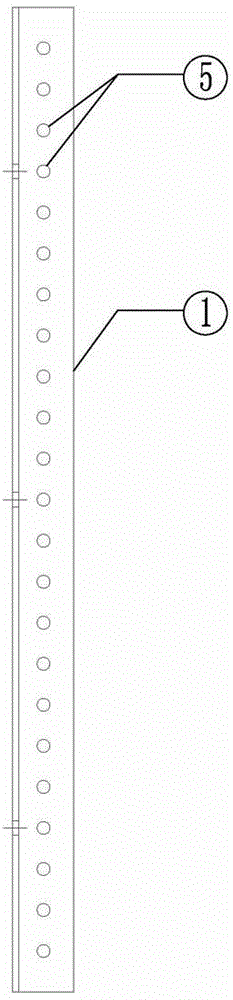
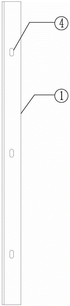
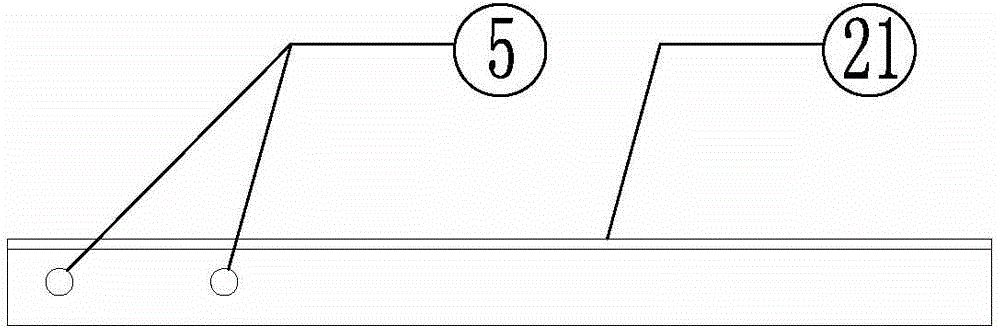
[0029] Embodiment 1: This embodiment is for the installation and use of cable brackets under the conditions of comprehensive pipe trenches, cable tunnels, and cable trenches. The column 1 and the cross arm 2 adopt angle steel, the back wall of the column 1 is 400mm apart and the waist-shaped connection hole 4 is punched, and the side wall is 50mm apart and the bolt connection hole 5 is drilled; the connection ends of the cross arm 2 are two 100mm apart. Bolt connection holes 5, and make the angle α between the connection line of the two bolt connection holes 5 and the horizontal line be 2 degrees; the reinforcement plate 3 is a steel plate, and three bolt connection holes are drilled on the reinforcement plate 3 5. Make the positions of the three bolt connection holes correspond to the bolt connection holes of the column and the cross arm, that is, the first bolt connection holes 351 and the second bolt connection holes 352 are arranged vertically and vertically at an interval ...

Embodiment 2

[0030] Embodiment 2: The column 1 described in this embodiment adopts channel steel, and the cross arm 2 adopts angle steel. The back wall of the column 1 is 400mm away from the waist type connection hole 4, and the side wall is 50mm apart and the bolt connection hole 5 is punched; Two bolt connection holes 5 with a distance of 100 mm are drilled at the connection end of the load 2. The reinforcing plate 3 is made of a steel plate. The first bolt connection holes 351 and the second bolt connection holes 352 are vertically arranged at an interval of 50 mm. The distance from the third bolt connection hole 353 is 100mm, and the column 1 is connected and fixed with the wall through the waist-shaped connection hole 4 with the expansion bolt 7; On the outer side of the steel column 1, the reinforcing plate 3 is placed between the column and the cross arm, and is closely attached to the back of the angle steel cross arm 2. There is no gap between the cross arm 2 and the reinforcing pl...

Embodiment 3

[0031] Embodiment 3: This embodiment is for the installation and use of the cable gantry in the case of the cable pipe well and the cable shaft. The gantry columns of the plumbing well and the vertical shaft are respectively fixed to the side and bottom of the wall to support the cables and adjust the layer spacing of the cable support, and adjust the height difference between the two ends of the plumbing well and the vertical shaft. Since the cables are often arranged in a square or horizontal manner, the cables 10 need to be fixed with hoops at a certain distance. The column 1 in this embodiment is the same as that in the second embodiment. and the hoop cross-arm 23, the two ends of the gantry cross-arm 22 and the hoop cross-arm 23 are punched with two bolt connection holes 5 at a distance of 100 mm, and the gantry cross-arm 22 and the hoop cross-arm 23 are connected in an external manner. Connect and fix with the column 1 respectively, install and connect the hoop 9 through...


PUM


Abstract

The invention discloses an assembling type movable cable holder used for a medium/high-voltage cable line in a long-distance channel. The assembling type movable cable holder used for the medium/high-voltage cable line in the long-distance channel comprises a stand column and a cross arm, wherein the rear wall of the stand column is provided with waist-shaped connection holes; the side wall adjacent to the rear wall is provided with bolt connection holes; the cross arm is provided with bolt connection holes. The assembling type movable cable holder is also provided with a reinforcing plate with bolt connection holes; the stand column and the cross arm are connected and fixed by the reinforcing plate, a gasket and bolts via the bolt connection holes. The cable holder disclosed by the invention has the characteristics of reasonable structure, economical cost, attractive appearance and the like and has obvious advantages on the aspects of processing, packaging, transportation, on-site installation, cable laying, joint arrangement flexibility, intensity stability, economy and the like, and various disadvantages and defects of the traditional holder are eliminated.

Description

technical field [0001] The invention relates to a bracket for supporting and fixing cables in the laying of cable lines in power transmission projects, in particular to an assembled movable cable bracket for laying medium and high voltage cable lines in long-distance passages. Background technique [0002] With the development of the economy, the implementation of large-scale urban cable line projects involves more and more laying of medium and high voltage cable lines in long-distance passages. Long-distance cable passages involve cable tunnels, municipal comprehensive pipe trenches, ring pipe jacking, cable trenches, When laying high-voltage cable lines in cable tunnels, cable trenches and other structures such as working wells, cable brackets are required to support and fix the cables and their accessories. The laying of cable lines in long-distance passages is complicated, with a large number of cable joints and hoops, tens of thousands of cable supports, and hundreds of...

Claims


Application Information

Patent Timeline
Patent Type & Authority Applications(China)
IPC IPC(8): F16L3/06
CPCF16L3/06
Inventor 李志良
Owner 云南宸晟电力设计咨询有限公司
Why Eureka
Try Eureka