Method for detecting work efficiency of PMD rubbing and twisting device for optical fibers

An optical fiber and working technology, which is applied in the field of inspecting the working effect of the optical fiber PMD twisting device, can solve the problems that the influence of the optical fiber PMD index is not obvious, maintain or improve the stability of the optical fiber PMD index, etc., and achieve the effect of simple operation and guaranteed stability

Active Publication Date: 2014-09-24
湖北凯乐量子通信光电科技有限公司
View PDF7 Cites 4 Cited by
  • Summary
  • Abstract
  • Description
  • Claims
  • Application Information

AI Technical Summary

Problems solved by technology

The current detection method is to detect the optical fiber polarization mode dispersion index through the detection instrument, but because the optical fiber preform manufacturing technology and the preform drawing technology are relatively mature...

Method used


Image

  • Method for detecting work efficiency of PMD rubbing and twisting device for optical fibers
  • Method for detecting work efficiency of PMD rubbing and twisting device for optical fibers
  • Method for detecting work efficiency of PMD rubbing and twisting device for optical fibers

Examples


Embodiment 1

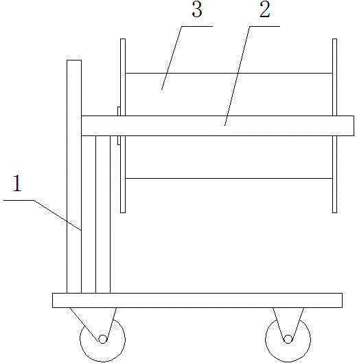
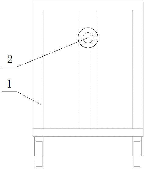
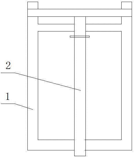
[0020] The method of testing the working effect of the optical fiber PMD twisting device requires three people to complete the work of testing the twisting of the optical fiber. The division of labor of the three people is: one of them is responsible for unwinding, one is responsible for sampling and testing the twisting times of the optical fiber, and one is responsible for recording the twisting data of the optical fiber. The specific test steps are as follows: (see attached Figure 1~3 ).

[0021] Step 1: Place the large-scale optical fiber 3 unloaded from the machine that has been twisted by the PMD twisting device on the cantilever shaft 2 of the large-scale optical fiber pay-off frame 1. The large-scale optical fiber 3 has not been screened and rewound.

[0022] Step 2: After removing 20m of the outer end of the twisted fiber wound on the large disk, the sampling person pinches the twisted fiber head tightly to ensure that the twist of the twisted fiber is not released. ...

Embodiment 2

[0027] The method of testing the working effect of the optical fiber PMD twisting device requires three people to complete the work of testing the twisting of the optical fiber. The division of labor of the three people is: one of them is responsible for unwinding, one is responsible for sampling and testing the twisting times of the optical fiber, and one is responsible for recording the twisting data of the optical fiber. The specific test steps are as follows: (see attached Figure 1~3 ).

[0028] Step 1: Place the large-scale optical fiber 3 unloaded from the machine that has been twisted by the PMD twisting device on the cantilever shaft 2 of the large-scale optical fiber pay-off frame 1. The large-scale optical fiber 3 has not been screened and rewound.

[0029] Step 2: After removing the outer end of the twisted fiber wound on the large disk for about 20m, the sampling person pinches the twisted fiber head tightly to ensure that the twist of the twisted fiber is not rel...


PUM


Abstract

The invention relates to a method for detecting work efficiency of a PMD rubbing and twisting device for optical fibers, and belongs to the technical field of optical fiber manufacturing. The method is a test for carrying out optical fiber actual twisting manually, optical fiber twisting samples with a length of 2 m are taken, two testing methods are adopted to test the directions and the times of twisting of the optical fiber twisting samples, a sine period curve chart is generated according to testing data, and then the oscillation amplitude and the frequency of a PMD rubbing and twisting wheel are adjusted according to the sine period curve chart. According to the method for detecting the work efficiency of the PMD rubbing and twisting device for the optical fibers, the operation effects of the PMD rubbing and twisting device can be detected macroscopically, PMD rubbing and twisting parameters can be adjusted effectively in time, and therefore monitoring on the operation effects of a high-speed rolling wheel clamping type optical fiber PMD rubbing and twisting device is achieved. The problem that waste products appear frequently in production due to insufficient monitoring is solved, and the gap that operation situations of the high-speed rolling wheel clamping type optical fiber PMD rubbing and twisting device cannot be monitored in a current optical fiber high-speed wire drawing technology is filled in.

Description

technical field [0001] The invention relates to a method for inspecting the working effect of an optical fiber PMD twisting device, belonging to the technical field of optical fiber manufacturing. Background technique [0002] Optical fiber communication is a communication method in which laser is used as the information carrier and optical fiber is used as the transmission medium. At present, optical fiber has become the main medium for information broadband transmission, and the optical fiber communication system will become the backbone of the national information infrastructure in the future. Especially today with the rapid development of information, ultra-large capacity and ultra-long-distance transmission technology is particularly important. The traditional G.652 single-mode fiber has been exposed to the situation of inability to meet the development needs of ultra-high-speed long-distance transmission networks. The development of new optical fibers It has become an...

Claims


Application Information

Patent Timeline
IPC IPC(8): G01M99/00G01M11/02
Inventor 孙贵廷韩向荣高德龙段和平李波
Owner 湖北凯乐量子通信光电科技有限公司
Why Eureka
Try Eureka