Optical fiber connector with long service life

A fiber optic connector, long-life technology, applied in the field of communication, can solve the problems of poor return loss index, unfavorable later operation, many disadvantages, etc., achieve good return loss index, improve service life, and increase the effect of air circulation

Inactive Publication Date: 2014-09-24
CHENGDU MAKEMODE COMM TECH
View PDF6 Cites 3 Cited by
  • Summary
  • Abstract
  • Description
  • Claims
  • Application Information

AI Technical Summary

Problems solved by technology

[0002] Although the straight-through connectors currently in use are very simple in structure, easy to implement, and low in cost, they have many disadvantages, such as strict requirements on the diameter of the optical fiber, strict requirements on the cut end face and cut length, and stricter requirements on the holding strength. Otherwise, any Any mismatch with the product will cause fluctuations in parameters
Since the return loss index is completely dependent on the condition of the cut end face of the fiber, the return loss index of the product is relatively poor, which requires high operator proficiency, which is not conducive to later operation
In addition, the current connectors are placed directly on the ground, especially in some wet places, the connectors are easily damaged and the current connectors cannot be rotated, which is not conducive to the insertion of optical fibers.

Method used


Image

  • Optical fiber connector with long service life
  • Optical fiber connector with long service life

Examples


Embodiment 1

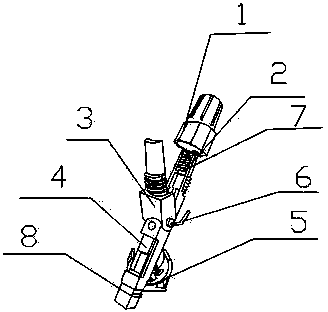
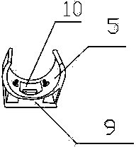
[0018] Such as Figure 1-2 As shown, the present invention includes a boot 1, a tailstock 2, a gland 3, an optical fiber cold connector 4, a moisture-proof seat 5 and a ceramic ferrule 8. One end of the tailstock 2 is socketed to the boot 1, and the other end is connected to the optical fiber at the same time. Cold joint body 4 and gland 3, gland 3 is positioned at the top of tailstock 2 and can rotate up and down around the connecting end of tailstock 2, gland 3 can rotate by being positioned at the rotary member 6 on the side of gland 3; The optical fiber cold splicer 4 is also connected to the ceramic ferrule 8 ; the moisture-proof seat 5 is located directly below the optical fiber cold splicer 4 . The moisture-proof seat 5 includes an arc-shaped support surface and a support column located below the arc-shaped support surface, and a square air hole 10 is arranged at the bottom of the arc-shaped support surface.

[0019] When using, put the tail sleeve into the outer sheat...

Embodiment 2

[0021] In this embodiment, on the basis of Embodiment 1, the preferred specific structure is as follows: the support column is a convex structure, and separate vertical plates are arranged between the two ends of the support column and the arc-shaped support surface, so that a ventilated space is formed on both sides of the support column. area. While ensuring that the support column can stably support the entire optical fiber cold splice body, it can also increase the air circulation under the cold splice body, better observe the situation under the cold splice body, and ensure the fast and accurate insertion of the fiber end face to achieve better return loss index.

[0022] Uniform fiber locking teeth 7 are arranged on the inner surface of the tailstock 2 , and fiber guide holes are arranged between the tailstock 2 and the optical fiber cold connector 4 . Ensure the accuracy and proper insertion of optical fibers.

[0023] The connecting end of the gland 3 is arranged in ...


PUM


Abstract

The invention discloses an optical fiber connector with the long service life. The optical fiber connector comprises a tail sleeve (1), a tail base (2), a gland (3), an optical fiber cold connector body (4), a damp-proof base (5) and a ceramic insertion core (8). One end of the tail base (2) is connected with the tail sleeve (1) in a sleeved mode, the other end of the tail base (2) is connected with the optical fiber cold connector body (4) and the gland (3), the gland (3) is located above the tail base (2) and can rotate up and down around the connecting end of the tail base (2), the gland (3) can rotate through a rotating part (6) located on the side face of the gland (3), the optical fiber connector body (4) is connected with the ceramic insertion core (8), and the damp-proof base (5) is located under the optical fiber cold connector body (4). By the adoption of the structure, the optical fiber connecting part can be isolated from the ground, the position where optical fibers are inserted can be rotated so as to facilitate insertion of the optical fibers and achieve rapid insertion, the connector is prevented from being affected with damp and damaged, and the service life of the connector is prolonged.

Description

technical field [0001] The invention relates to the communication field, in particular to an optical fiber connector with long service life. Background technique [0002] Although the straight-through connectors currently in use are very simple in structure, easy to implement, and low in cost, they have many disadvantages, such as strict requirements on the diameter of the optical fiber, strict requirements on the cut end face and cut length, and stricter requirements on the holding strength. Otherwise, any Any mismatch with the product will cause fluctuations in parameters. Since the return loss index is completely dependent on the condition of the cut end face of the optical fiber, the return loss index of the product is relatively poor, which requires a high level of operator proficiency, which is not conducive to the later operation. In addition, the current connectors are placed directly on the ground, especially in some humid places, the connectors are easily damaged ...

Claims


Application Information

Patent Timeline
Patent Type & Authority Applications(China)
IPC IPC(8): G02B6/38
Inventor 郭仁祥蔡义炜钱兴容王梅
Owner CHENGDU MAKEMODE COMM TECH
Why Eureka
Try Eureka